Artikelaktionen
GRAPP 2006
High-Level Modeling of Multimodal Interaction Techniques Using NiMMiT
- Joan De Boeck Hasselt University, Expertise Centre for Digital Media and Transnationale Universiteit Limburg
- Davy Vanacken Hasselt University, Expertise Centre for Digital Media and Transnationale Universiteit Limburg
- Chris Raymaekers Hasselt University, Expertise Centre for Digital Media and Transnationale Universiteit Limburg
-
Karin Coninx
 Hasselt University, Expertise Centre for Digital Media and Transnationale Universiteit Limburg
Zusammenfassung
- veröffentlicht: 28.08.2007
Keywords
- Interaction Metaphors
- Interaction Techniques
- Interactive Virtual Environment
- Model-Based Design
- Multimodal Interaction
- DOI: 10.20385/1860-2037/4.2007.2
- URN: urn:nbn:de:0009-6-11615
-
swd:
- 4830853-5
- 4399931-1
High-Level Modeling of Multimodal Interaction Techniques Using NiMMiT
urn:nbn:de:0009-6-11615
Abstract
The past few years, multimodal interaction has been gaining importance in virtual environments. Although multimodality renders interacting with an environment more natural and intuitive, the development cycle of such an application is often long and expensive. In our overall field of research, we investigate how model-based design can facilitate the development process by designing environments through the use of high-level diagrams. In this scope, we present ‘NiMMiT′, a graphical notation for expressing and evaluating multimodal user interaction; we elaborate on the NiMMiT primitives and demonstrate its use by means of a comprehensive example.
Keywords: Interaction Techniques, Interaction Metaphors, Multimodal Interaction, Interactive Virtual Environment, Model-Based Design
Subjects: Multimodal System, Virtual environments
Designing an intuitive and easy to use computer application is not a straightforward undertaking. In spite of the extensive knowledge that we have at our disposal nowadays, the complications are even more pronounced when 3D interaction is required. Although humans interact daily in a (real) 3D world, it turns out that moving into a virtual 3D world causes usability problems to surface. Numerous interaction techniques have been investigated in order to overcome these issues, while trying to create a more natural interaction. Despite all efforts, each technique still has its own strengths and weaknesses.
User tasks in a 3D world can be divided in three classes [ Esp96 ]: navigation, object selection and object manipulation. A few well-known navigation metaphors are Flying Vehicle and Scene In Hand [ WO90 ]. Object selection is for instance realized by a virtual hand or ray selection [ LG94 ]. And finally, common object manipulation metaphors include virtual hand, HOMER [ BH97 ] and Voodoo Dolls [ PSP99 ]. A comprehensive overview of the most important metaphors is found in [ DBRC05 ].
When designing interactive 3D interfaces, we are presented with a large number of possibilities: choosing, combining and adapting existing solutions, or even developing a brand-new custom-made solution. As the acceptance of an interaction technique (IT) often depends on the actual application set-up, and the user′s experience and foreknowledge, the most appropriate method to evaluate a particular solution is testing it in a user experiment. However, testing several alternatives implies that each solution must be fully implemented.
A solution to shorten the development cycle of a user interface, widely adopted in the domain of 2D and mobile user interfaces, is model based user interface design (MBUID) [ DS00 ]. An overview of model-based processes [ CLC04 ] reveals several common properties. Nearly all processes start with a task model [ Pat00 ] and evolve towards the final user interface, using an incremental approach. During each increment, a model is converted into a new one by means of an automatic transformation (through mapping rules) or manual adaptation by the designer. Applying such a process to the development of multimodal 3D interfaces [ CRC05 ] points out the need to specify interaction in a high-level manner, rather than having to manually code the techniques.
Therefore, we propose a high-level graphical notation, that should allow:
-
designers to communicate about the functionality of an interaction technique, using an easy-to-read diagram,
-
an application framework to interpret the diagram, so it can be executed and tested.
The notation must provide adequate low-level information for a software framework to execute the diagrams automatically, but it also needs to be sufficiently high-level and easily readable for a designer to reason about the IT.
In this paper, we propose a graphical notation called ‘NiMMiT′, together with some tools, which facilitate the design and adaptation of multimodal interaction techniques with a minimum of coding effort. NiMMiT allows a designer to quickly test alternatives or easily adapt existing solutions according to the findings of a usability evaluation, shortening the development cycle significantly. Automatic execution of the interaction techniques is supported by interpreting the diagram representation. Moreover, the high-level description introduces a way to easily reuse solutions.
In the next section, we describe some existing notations, each with their particular strengths and weaknesses. Thereafter, we clarify the requirements to describe an IT and we explain the basic primitives of our notation, which combine the aforementioned requirements. In section 3 , we show how diagrams are executed by a framework. Finally, we illustrate the notation by means of an extensive example and we explain how NiMMiT supports quick evaluations.
Literature describes some relevant notations, which can roughly be divided into two families: state driven and data driven approaches. State driven notations, such as State Charts [ Har87 ] and Petri-nets [ Pet62 ] are based on the formal mechanisms of finite state machines. A basic element of such a notation is a state transition, which has the general form ‘when event a occurs in state A, the system transfers to state B, if condition C is true at that time′. Some state-driven notations are extended to support data flow. Examples are Colored Petri-nets [ Jen94 ] and Object Petri-nets [ Val98 ]. Other notations, such as Labview (a graphical programming language) [ Nat06 ] or UML [ Amb04 ] focus specifically on the data- or object flow. Their basic element is ‘activity′ supporting data input and output. The execution of an activity is driven by the presence of valid data on the input ports.
In the domain of user interaction, various notations, for the most part based on the aforementioned solutions, are optimized for a specific purpose. Interaction Object Graphs [ Car97 ] and ICO [ NPB05 ][ PB94 ] are mainly state driven, while InTml [ FGH02 ] and ICon [ DF04 ][ HDD04 ] are two very similar notations, using a data flow architecture. The diagrams consist of filters, performing the basic actions of the interaction. Each filter contains input and output ports: output ports can be connected to input ports of other filters. The control flow of the diagram is directed by the data, since a filter is executed when it receives a legal value on all of its input ports.
In a preparatory study, we have conducted several experiments, trying to describe existing interaction metaphors using different notations. Although the experiments were rather informal, we notice the following:
-
while describing a technique using a state driven notation, the lack of data handling was restricting, especially when automatic execution of the IT is required,
-
using one of the data flow based notations, very complex structures have to be designed in order to enable or disable certain parts of the IT, which is essential for describing interaction, as well.
For a more formal evaluation, we refer the interested reader to our ongoing work [ DVRC06 ] in which we are performing a second-phase evaluation of the different notations, using cognitive dimensions [ Gre89 ].
Based upon our findings, we conclude that none of the aforementioned notations entirely fulfils all our requirements. Therefore, we developed a graphical notation which is both state and data driven. This allows us to maintain data flow, while inheriting the formalism of state charts, which is necessary for interpretation and execution of diagrams. The notation is called NiMMiT, a Notation for Multimodal Interaction Techniques. The strengths of this solution lies in the easy-to-learn and easy-to-read diagrams, which provide an unambiguous description of the interaction and can be interpreted by an application at runtime.
In the next paragraph, we first clarify our vision on interaction. We maintain a rather abstract approach, which is formulated as a set of requirements, serving as a guiding principle throughout our work on interaction modelling. Thereafter, we shortly explain the basic primitives of NiMMiT.
In our opinion, as a result of our preceding experiments, a notation to describe interaction techniques must support the following requirements:
-
it must be event driven,
-
state driven,
-
data driven,
-
and must support encapsulation for hierarchical reuse.
In the next subsections, we motivate the importance of these requirements in the context of interaction techniques.
Interaction techniques are inherently driven by user-initiated actions, which we define as events. Since human interaction is multimodal by nature, it can be interpreted as a combination of unimodal events (e.g. pointer movement, click, speech command, gesture, etc.). An event has the following properties:
-
a source, indicating the modality and/or abstract device that caused it (speech, pointing device, gesture, etc.),
-
an identification, defining the event itself (button click, speech command, etc.),
-
parameters, giving additional information about the event (e.g. the pointer position).
Events can be seen as “the initiators” of different parts of the interaction.
While interacting with it, the system not always has to respond to all available events. Most of the time, specific events must have occurred before other events are enabled. For instance, the user first needs to click the pointer′s button, before being able to drag an object. Therefore, we perceive an interaction technique as a finite state machine, in which each state defines to which set of events the system will respond. The occurrence of an event also initiates a state transition. In our example, the dragging technique consists of two states. In a first state, the IT awaits a click, before moving to the second state. The second state responds to pointer movements and executes a state transition to itself.
Limiting our vision on interaction techniques to a finite state machine would be too restrictive. After analyzing several interaction techniques in 3D environments, it became clear that throughout the execution of an interaction some indispensable data flow occurs. A common sequence of actions is first selecting an object and afterwards moving that object around. Obviously, certain data must be transferred between the different tasks of the IT. Therefore, a notation to describe interaction techniques should support data flow.
Some subtasks of interaction techniques recur rather frequently. Selecting objects is an example of such a very common component. When modelling a new IT, the designer should be able to reuse descriptions that were created earlier. That way, recurring components do not have to be modelled repeatedly. In other words, the notation should support encapsulation of entire diagrams. In this way, existing diagrams can be reused as a subtask of a new description. Using such building blocks contributes significantly to more efficient development.
Figure 1. NiMMiT basics. (a) Start state with possible events. (b) Task chain. (c) Data flow between tasks and to a label.
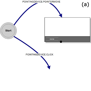
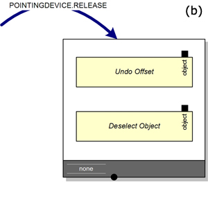
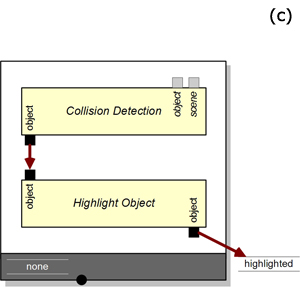
Figure 2. State transition and conditional state transition. (a) State transition. (b) Conditional state transition
States and events. Since the NiMMiT notation is state and event driven, a diagram can basically be considered a state chart. An interaction technique is always initiated in the starting state. A state responds to a limited set of events, such as a speech recognition, a pointer movement, a button click, etc. The recognition of an event causes a task chain to be executed, as shown in figure 1(a) .
Events can be related to each other with ′and′ or ′or′ relations, as shown in figure 8(b) and figure 8(c) . This is explained in more detail in section 4.5 . We propose Nigay′s Melting Pot principle to resolve the synchronization problem [ NC95 ].
Task chain and tasks. A task chain is a strictly linear succession of tasks. Figure 1(b) shows a task chain containing two tasks. The next task in the chain is executed if and only if the previous task has been completed successfully. The set of possible tasks obviously depends on the application domain; in each particular case, the most common tasks should be predefined by the system (section 3.2 ). Clearly, it is impossible to predefine every conceivable task. Therefore, we provide the designer with the possibility to add custom tasks by means of a scripting language.
Data flow, data types and labels. In a task-chain, tasks can pass data from one to another. Therefore, each task provides input and output ports. The port′s shape indicates its data type, and only ports of the same type can be linked to each other. As our first concern is to keep NiMMiT as simple as possible, we prefer a limited set of data types: numbers, strings, Booleans, and a few domain specific types, such as (in our case) position and rotation.
An output port of a preceding task is typically connected to an input port of a next task. These input ports are either required or optional. If a required input port receives an invalid value, the entire task chain is cancelled. To share data between tasks in different task chains, or to store data for later reuse, we provide high-level variables in the form of labels (fig 1(c) ). The content of a label is maintained as long as the NiMMiT diagram is operational; its scope is the entire diagram.
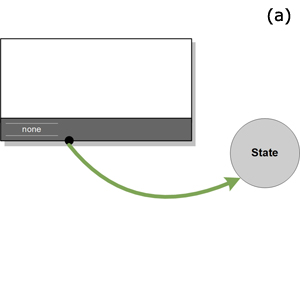
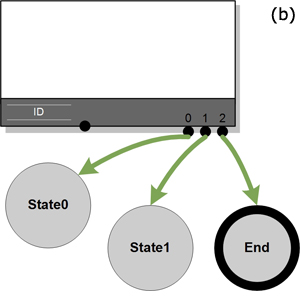
State transition and conditional state transition. After a task chain has been successfully executed, a state transition takes place (fig 2(a) ). The IT moves either to a new state or back to the current state (in a loop). In a new state, the interaction technique may respond to another set of events. A task chain can have multiple state transitions associated with it; the value of the chain′s label indicates which transition should be executed. Figure 2(b) shows a task chain with a conditional label ‘ID′ and three possible state transitions.
Encapsulation for hierarchical use. Since interaction techniques have an interface similar to the atomic tasks in a task chain, an IT can be hierarchically used as a task in a task chain. When a such a task is activated, the execution of the current IT is temporarily suspended and saved on a stack, waiting for the new IT to finish.
As described in the previous section, NiMMiT can be used to unambiguously visualize an interaction metaphor. It is beyond the scope of this paper to explain the overall model-based approach for Virtual Environments (VE) development [ CRC05 ] in which our NiMMiT research fits. Since the notation can be used to evaluate and adapt interaction techniques during the development phase, a set of tools is necessary to exploit the full benefits of NiMMiT. An easy-to-use NiMMiT editor and an interpreter supporting ‘automatic execution′ of diagrams are indispensable. In the next sections, we elaborate on these aspects of our current NiMMiT framework.
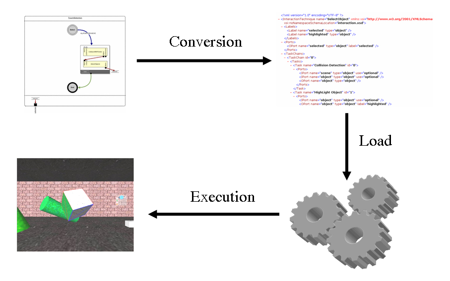
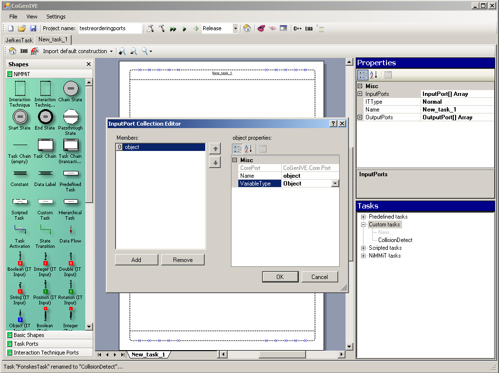
In a first step, a designer must be able to easily create and edit diagrams. Therefore, a NiMMiT editor is indispensable. Figure 3(b) shows a screenshot of the editor: we have chosen to integrate a VISIO-component to quickly support the simple editing features that are obviously expected (such as drag and drop, copy and paste, etc). The application constantly evaluates the VISIO diagram and asserts the syntactical correctness.
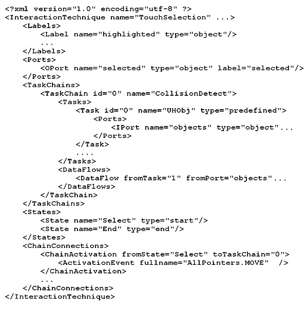
To allow a framework to execute an interaction technique, the NiMMiT editor converts the diagram to a NiMMiT-XML file (as shown in figure 4 ), which can be easily loaded and interpreted at run-time.
The runtime interpretation engine consists of a central manager which maintains the state, listens to events, executes task-chains and keeps track of labels. It loads the XML and directs the application or software framework. The design of the NiMMiT framework allows it to operate apart from our existing VR research framework, so it can be readily adopted in other frameworks or applications.
The main actions of an interaction technique are obviously situated in the tasks. Dependent on the framework and the application domain in which NiMMiT is applied, different sets of tasks are conceivable. Our implementation, focussing on interaction in 3D environments, provides several predefined tasks, such as ‘selecting′, ‘moving′ and ‘deleting′ objects, ‘collision detection′, etc. When different actions are required, a custom task can be created. Custom tasks are coded using a scripting language, in our case LUA scripting [ IdFC96 ], which is compiled or interpreted at runtime. However, other implementations of a NiMMiT interpreter may include a different scripting language.
Interaction is initiated by the user, who communicates with the environment through physical devices. Since the number of different device set-ups is immense, NiMMiT provides a device abstraction through the use of events: devices are grouped in ‘families′ according to the events they generate (e.g. pointing, navigation, speech and gesture recognition). Devices within a family share some significant properties and generate interchangeable events. As a result of this abstraction, switching between devices in the same family does not affect the interaction, and hence the NiMMiT diagram does not require any changes. On the other hand, when a pointing device is replaced by speech input, a small change to the diagram (changing the event arrow) is necessary.
This section illustrates our notation by means of a practical example. First, we describe ‘Object-In-Hand Metaphor′, the two-handed interaction technique used in our example. Elaborating on the diagrams, we start with the interaction technique for selecting an object. The result will be hierarchically used in the diagram of the non-dominant hand′s interaction. Finally, the collaboration with the dominant hand is discussed briefly, and we consider the support for multimodal interaction.
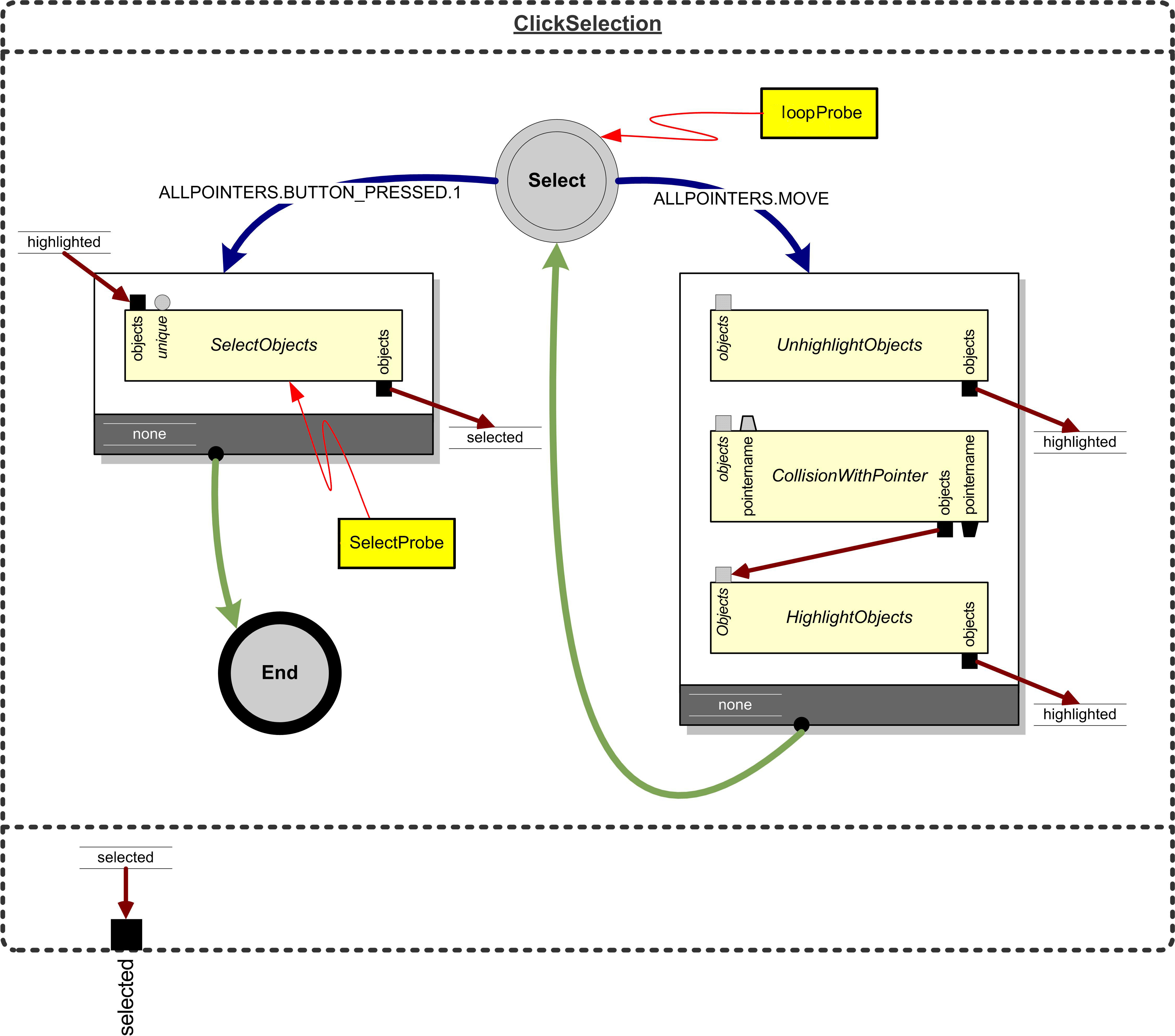
Figure 6. Object-in-Hand metaphor. (a) Grabbed object. (b) Hand brought close. (c) Hand rotated. (d) Selected object. (e) Object-in-Hand. (f) Rotated object.
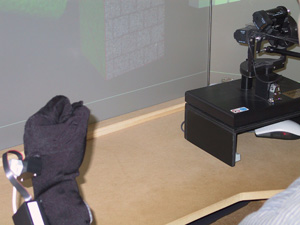
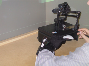
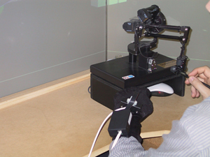
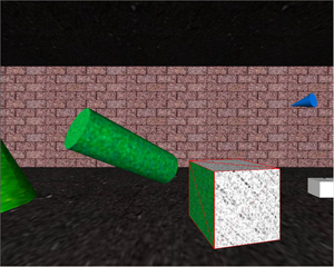
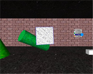
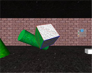
As a case study, we have chosen to elaborate on the Object-In-Hand metaphor, presented and evaluated in [ DBCDW04 ]. After an object has been selected, the user can ‘grab′ it by bringing the non-dominant hand′s fist close to the pointing device in the dominant hand. This causes the selected object to move towards the center of the screen, where it can be manipulated by the dominant hand (fig 6 ). In our current implementation, we allow the user to select the object′s faces and change their texture. Since the Object-In-Hand metaphor requires the user to utilize both hands, this example also illustrates a synchronization mechanism between different interaction techniques.
As a first step, the user is required to select an object. Quite a number of selection metaphors exist, presenting the designer several alternatives. We have chosen a virtual hand metaphor: highlight the object by touching it and confirm the selection by clicking. This interaction component can be easily expressed in the NiMMiT notation, as depicted in figure 5 .
The interaction technique starts in the state ‘Select′ responding to the following events: a pointer movement and a click. Each time the pointer moves (and the button is not clicked), the rightmost task chain is executed. This chain contains three consecutive, predefined tasks: unhighlight any highlighted objects, check for collisionsand highlight an object if necessary. The first task has an optional input; if not provided, all highlighted objects are released and the output returns an empty list. The second task contains two optional input ports, providing the objects and pointers that should be taken into consideration by the collision detection. If optional inputs are connectionless, default values are used: collisions are calculated between all pointers and objects in the environment. The colliding objects, if any, are obtainable through the output port.
The final task, highlighting the colliding objects, will only be executed when all of the required input ports receive an appropriate value. If the previous task does not detect a collision, this prerequisite is not satisfied and the chain is aborted. Consequently, the system returns to the state ‘Select′ and awaits new events. If the highlighting task does receive a proper value, the objects are highlighted and results are stored in the label ‘highlighted′. Finally, a task transition returns the system to the state ‘Select′.
While the system resides in the state ‘Select′, click events cause the leftmost task chain to be executed. It contains only one task: selecting an object. If the previous chain was successfully completed, the task selects the highlighted object, received by connecting the label ′highlighted′ to the input port. Additionally, the task stores the selected object in a new label, ‘selected′. In case the label ‘highlighted′ contains no viable value (e.g., no object was highlighted), the chain is aborted, returning the system to the state ‘Select′.
When the second task chain finishes successfully, a final state transition occurs. The system moves to the ending state and the selected object is outputted, using the label ‘selected′. At that moment, the interaction technique is completed. In the next section, we demonstrate how this entire diagram can be reused as a single, hierarchical task.
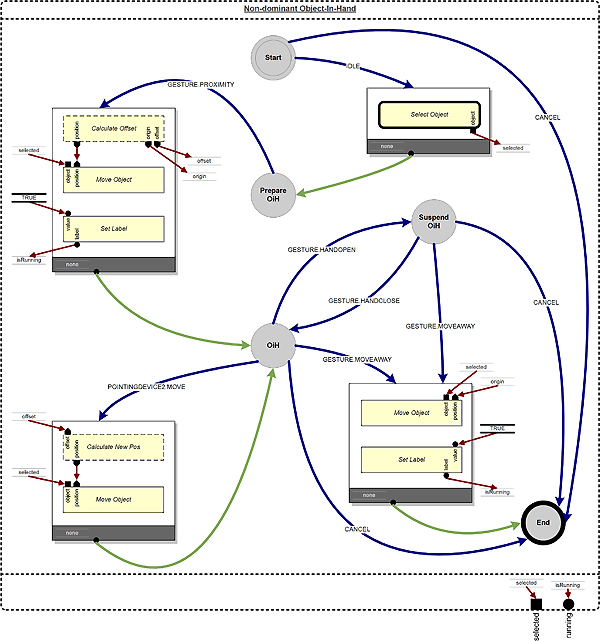
After an object has been selected using the aforementioned selection technique, it can be ‘grabbed′ with the non-dominant hand. By bringing the fist close to the dominant hand, the object moves to the center of the screen, where it can be manipulated by the dominant hand.
Running the diagram in figure 7 triggers the starting state. As soon as an ‘idle′ event occurs, which happens continuously while no other events are generated, the first task chain executes. The only task in this chain is our previously defined selection technique. While this hierarchical task is active, the execution of the current interaction technique is suspended. When the selection task is completed, the current interaction technique resumes, and the outputted result is stored in the label ‘selected′. Next, a state transition to ‘Prepare OiH′ takes place.
This state awaits either a gesture or a cancel event. The gesture is defined as ‘a closed non-dominant hand brought in the proximity of the dominant hand′ and triggers the second task chain. The first task, a scripted task, calculates the offset between the virtual position of the non-dominant hand and the centre of the screen. The task requires the selected object as an input. The object′s initial position, the offset and the new position are outputted and stored in labels. The next task simply moves the object to its new position. The final task sets a label to ‘true′; the label is needed for synchronization, explained in section 4.4 .
Eventually, the system ends up in the state ‘OiH′, awaiting an appropriate event. As soon as the user opens his/her hand (recognized as a gesture), a transition (without task chain) to ‘suspend OiH′ occurs. When the hand closes again, the ‘OiH′-state is reactivated. These state transitions implement clutching and declutching, allowing the rotation of an object beyond the physical constraints of the user′s arm. ‘OiH′ also responds to movements of thenon-dominant hand. In the corresponding task chain, these movements are mapped to the object′s position. Finally, both states respond to the withdrawal of the non-dominant hand (another gesture). The associated task chain restores the objects initial position and resets the label ‘isRunning′.
The interaction of the dominant hand, which is described in a new NiMMiT diagram, depends on the state of the non-dominant hand: when the non-dominant hand is not in the proximity of the dominant hand, it makes no sense to enable the dominant hand′s interaction. Therefore, the label ‘isRunning′, outputted by the ‘Non-dominant Object-in-Hand′ diagram, is connected to an input port of the new diagram. Based on the value of this label, the execution of both diagrams are synchronized.
Figure 8. Multimodal support within NiMMiT. (a) Sequential MM. (b) Simultaneous MM. (c) Equivalence.
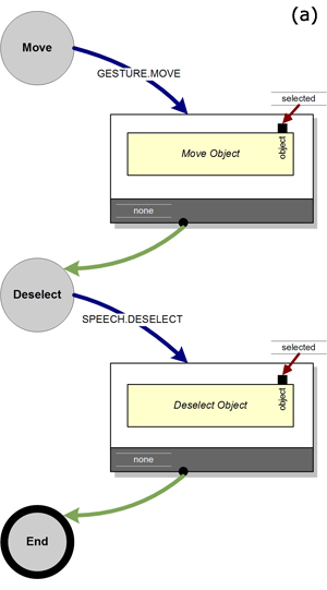
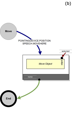
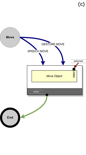
Since we support several ‘families′ of devices, as described in section 3.3 , multimodality is accomplished by combining events from different families. Our example shows how direct manipulation, gestures and menu commands can cooperate, but more advanced multimodal interaction is certainly possible. Based on the notion that multimodal interaction is caused by several unimodal events, NiMMiT supports sequentially multimodal and simultaneous multimodal interaction [ SBC02 ], as well as equivalence between the modalities [ CNS95 ]. Sequential multimodality can be implemented by defining subsequent states that respond to events coming from different sources. In figure 8(a) , an object is first moved using a gesture and, in the next state, deselected using speech. Simultaneous multimodality is supported by defining an AND-relation between affecting events: the user moves an object by combining a pointer movement and a speech command, as shown in figure 8(b) . Finally, equivalent modalities are permitted by using the OR-relation. Figure 8(c) illustrates a movement action, achieved by either a speech-command or a gesture.
Since simultaneous events, as shown in 8(b) , never occur at the exact same time, we have adopted the Melting Pot principle, as described by Nigay et al. [ NC95 ]. Moreover, multimodal interaction may require the parallel execution of different aspects of an interaction technique. One NiMMiT diagram on itself does not support concurrency. However, multiple diagrams may be executed at the same time. In that case, synchronization issues are solved by exchanging labels between the diagrams, as shown in section 4.4 .
In the previous sections, we have shown how an interaction technique can be executed by feeding a NiMMiT diagram to a NiMMiT interpreter. This approach can save a designer time that he or she would otherwise have spent writing programming code. To exploit this advantage even further, NiMMiT is extended to support automated data gathering and processing. It is well known that usability testing often requires ad-hoc adaptations to the application code, in order to log data for statistical analysis. Consequently, adding automation to usability evaluation has many potential benefits, such as time efficiency and cost reduction [ IH01 ]. In this section, we explain how NiMMiT is extended with three primitives: probes, filters and listeners. A more detailed description can be found in [ CCDBR06 ].
A probe is a measurement tool, connected to a particular primitive in a NiMMiT diagram, much like an electrician placing a voltmeter on an electric circuit. Probes can be associated with a state, task chain, task or input/output port. A probe returns relevant data regarding the primitive it is attached to:
-
state probes return all events occurring while the state is active,
-
task chain probes return the activation event(s) of the task chain, its status (executed, interrupted or failed), and the value of the conditional label,
-
task probes indicate whether or not the execution of the task succeeded,
-
port probes return the current value of the port.
Probes connected to primitives which were inactive during the current phase of the interaction, return empty. The example given in figure 5 shows a probe connected to the ‘Select′-state (shaded rectangle with the zigzag arrow).
NiMMiT′s probes are a useful tool for debugging an interaction technique. By attaching a probe to all states of a diagram, one can for instance evaluate the correct order of execution or monitor the events being recognized. In addition, output of tasks can be verified using port probes. This approach leads to a significant reduction of the time necessary to discover logical errors in a diagram. However, on its own, the raw output of a probe is not suitable to collect information during a usability test.
To adapt data coming from a probe, we define filters. Filters are meta-probes collecting and processing the output of one or more probes. Since filters are in fact specialized probes, they can be chained one after another. Filters can rearrange or summarize data, or wait until data arrives for the first time, and then start, stop or pause a timer. The latter approach is for instance useful for measuring the time spent between two states of the interaction.
Although the data necessary for a usability evaluation can be very divergent, often the same patterns return: summarizing a distance, counting the elapsed time, logging success or failure, etc. Therefore, NiMMiT provides a standard set of commonly used filters, including (conditional) counting and distance or time measuring. Experienced users are allowed to develop custom filters, according to their more advanced needs. In the near future, we will extend our approach so that filters can be implemented using the same scripting language. As filters can be connected to multiple probes, even across different diagrams, they are not visualized in a NiMMiT diagram.
Filters and probes only collect and structure information. By connecting listeners to a probe or filter, output can be redirected to any output medium. The default listeners can write data to a file or text window, or even send it over the network to an external computer or a database system. The outputted data can serve as input for the statistical analysis of the user experiment. As with filters, experienced developers can provide custom listeners, exporting to a suitable medium. For the same reason as filters, listeners are not represented in the NiMMiT diagram.
The NiMMiT diagram in figure 5 contains two probes: the state probe ‘loopProbe′, providing a list of recognized events, and the task probe ‘SelectProbe′, returning an empty value while the right-hand task chain is being executed. When the user clicks the button, this second probe indicates whether or not the task ‘SelectObjects′ has been successfully completed. The outputs can be redirected using a listener, providing the designer a useful debugging tool.
In order to collect data for a usability evaluation, the standard ‘Timer filter′ can be applied. Connected to both probes, this filter starts a timer as soon as the ‘loopProbe′ generates its first output, and stops counting when the ‘SelectProbe′ outputs its first value. The filter calculates the time elapsed between the first and second trigger. Using an appropriate listener, the outputs can be redirected for statistical processing. An elaborated example of one of our user experiments conducted using NiMMiT, probes and filters can be found in [ CCDBR06 ].
This paper presents NiMMiT, a graphical notation which facilitates the design of multimodal interaction techniques with a minimum of coding effort. The notation allows a designer to quickly test alternative solutions or easily adapt existing solutions according to the findings of a usability evaluation, shortening the development cycle significantly.
NiMMiT, based on both state and data driven primitives, provides device abstraction through the use of events and supports an hierarchical build-up. The unambiguous modelling of an interaction technique allows diagrams to be interpreted and executed by our NiMMiT framework, which focuses on interactive 3D environments. Furthermore, we extended the notation to support automated data gathering and processing, which provides useful information for debugging and usability evaluations.
We illustrated the expressiveness of NiMMiT by modelling the two-handed ‘Object-In-Hand′-metaphor, but the implementation of the runtime interpretation engine has also been extensively tested on well known interaction techniques, other than described in this paper. Further research will demonstrate the usability/usefulness of NiMMiT. Moreover, we intend to integrate NiMMiT in other frameworks to prove the generality of our solution.
Part of the research at the Expertise Center for Digital Media is funded by the ERDF (European Regional Development Fund), the Flemish Government and the Flemish Interdisciplinary institute for Broadband Technology (IBBT). The VR-DeMo project (IWT 030248) is directly funded by the IWT, a Flemish subsidy organization.
The authors also want to thank Erwin Cuppens for his valuable contribution to the implementation.
[Amb04] Object Primer, The Agile Model-Driven Development with UML 2.0, Cambridge University Press, 2004, isbn 0-521-54018-6.
[BH97] An Evaluation of Techniques for Grabbing and Manipulating Remote Objects in Immersive Virtual Environments, Proceedings of the Symposium on Interactive 3D Graphics, 1997, April 27-30, Providence, RI, USA, pp. 35—38, isbn 0-89791-884-3.
[Car97] Interaction Object Graphs: An Executable Graphical Notation for Specifying User Interfaces, Formal Methods for Computer-Human Interaction, Springer-Verlag, 1997, pp. 141—156.
[CCDBR06] Integrating Support for Usability Evaluation into High Level Interaction Descriptions with NiMMiT, Proceedings of 13th International Workshop on Design, Specification and Verification of Interactive Systems (DSVIS'06), 2006, , Dublin, Ireland, issn 0302-9743.
[CLC04] Dynamo-AID: A Design Process and a Runtime Architecture for Dynamic Model-based User Interface Development, 9th IFIP Working Conf. on Engineering for Human-Computer Interaction jointly with 11th Int. Workshop on Design, Specification, and Verification of Interactive Systems EHCI-DSVIS 2004, pp. 77—95, Springer-Verlag, 2004, July 11-13, Hamburg, Germany, isbn 3-540-26097-8.
[CNS95] Four Easy Pieces for Assessing the Usability of Multimodal Interaction: The CARE Properties, Proceedings of INTERACT95, June 1995, Lillehammer, pp. 115—120.
[CRC05] A Model-Based Design Process for Interactive Virtual Environments, Proceedings of 12th International Workshop on Design, Specification and Verification of Interactive Systems (DSVIS'05), 2005, pp. 225—236, Newcastle upon Tyne, UK, July 13-15, isbn 3-54034145-5.
[DBCDW04] Multisensory interaction metaphors with haptics and proprioception in virtual environments, Proceedings of the third ACM Nordic Conference on Human-Computer Interaction (NordiCHI 2004), 2004, October, Tampere, FI, pp. 189—197, isbn 1-58113-857-1.
[DBRC05] Are Existing Metaphors in Virtual Environments Suitable for Haptic Interaction, Proceedings of 7th International Conference on Virtual Reality (VRIC 2005), 2005, pp. 261—268, 20-24 Apr, Laval, France, isbn 2-915730-3-0.
[DVRC06] Comparing NiMMiT and Data-Driven Notations for Describing Multimodal Interaction, Tamodia 2006, 2006, Diepenbeek, Belgium, October.
[DF04] Support for input adaptability in the ICON toolkit, Proceedings of the 6th international conference on multimodal interfaces (ICMI04), 2004, State College, PA, USA, pp. 212—219, isbn 1-58113-995-0.
[DS00] User Interface Declarative Models and Development Environments: A Survey, DSV-IS 2000, 2000, Limerick, Ireland, pp. 207—226, Springer, Lecture Notes in Computer Science, , isbn 3-540-41663-3.
[Esp96] User Interfaces for virtual reality systems, Human Factors in Computing Systems, CHI96 Conference Tutorial Notes, Sunday, April 14, 1996, pp. 340—341, 0-89791-832-0.
[FGH02] InTml: A Description Language for VR Applications, Proceedings of Web3D'02, 2002, February, Arizona, USA, pp. 53—58, isbn 1-58113-468-1.
[Gre89] Cognitive Dimensions of Notations Proceedings of the fifth conference of the British Computer Society, Human-Computer Interaction Specialist Group on People and computers V, pp. 443—460, 1989, Cambridge, UK, isbn 0-521-38430-3.
[Har87] Statecharts: A visual formalism for complex systems, Science of Computer Programming, (1987), 231—274, issn 0167-6423.
[HDD04] The MaggLite Post-WIMP Toolkit: Draw It, Connect It and Run It, Proceedings of the 17th ACM Symposium on User Interface Software and Technologies (UIST 2004), 2004, Santa Fe, New Mexico, USA, pp. 257—266, isbn 1-58113-957-8.
[IdFC96] LUA an extensible extension language, Software: Practice And Experience (1996), 635—652, issn 0038-0644.
[IH01] The State of the Art in Automating Usability Evaluation of User Interfaces, ACM Computing Surveys, (2001), no. 4, pp. 470—516, issn 0360-0300.
[Jen94] An Introduction to the Theoretical Aspects of Coloured Petri Nets, A Decade of Concurrency, Lecture Notes in Computer Science Vol. 803, W.-P. de Roever and G. Rozenberg (eds.), 1994, Springer-Verlag, pp. 230—272.
[LG94] JDCAD: A Highly Interactive 3D Modeling System, Computer and Graphics, (1994), no. 4, 499—506, issn 0097-8493.
[Nat06] National Instruments LabView, www.ni.com, June 2006, last visited August 28th, 2007.
[NC95] A Generic Platform for Addressing the Multimodal Challenge, Proceedings of ACM CHI'95 Conference on Human factors in Computing Systems, 1995, May 7-11, Denver, Colorado, USA, pp. 98—105, issn 0-201-84705-1.
[NPB05] A Formal Description of Multimodal Interaction Techniques for Immersive Virtual Reality Applications, Proceedings of Tenth IFIP TC13 International Conference on Human-Computer Interaction, September 12-16, 2005, Rome, IT, pp. 170—183, isbn 3-540-28943-7.
[Pat00] Model-Based Design and Evaluation of Interactive Applications, Springer-Verlag, 2000, isbn 1-852-33155-0.
[PB94] Petri net based design of user-driven interfaces using the interactive cooperative objects formalism, Interactive Systems: Design, Specification, and Verification, 1994, Springer-Verlag, pp. 383—400, isbn 3-540-59480-9.
[Pet62] Fundamentals of a Theory of Asynchronous Information Flow, IFIP Congress, 1962, pp. 386—390.
[PSP99] Voodoo Dolls: seamless interaction at multiple scales in virtual environments, Proceedings of symposium on interactive 3D graphics, 1999, April 26-28, Atlanta, GA, USA, pp. 141—145, isbn 1-58113-082-1.
[SBC02] The Effect of Prolonged use on Multimodal Interaction, Proceedings of ISCA - Workshop on Multimodal Interaction in Mobile Environments, 2002, Kloster Irsee, Germany.
[Val98] Petri Nets As Token Objects: an Introduction to Elementary Object Nets, 19th International Conference on Application and Theory of Petri Nets (ICATPN'98), 1998, Springer, June, Lissabon, Portugal, Lecture Notes In Computer Science Vol. 1420, pp. 1—25, isbn 3-540-64677-9.
[WO90] Exploration and Virtual Camera Control in Virtual Three Dimentional Environments, Computer Graphics, (1990), no. 2, isbn 0-89791-351-5.
Volltext 
-
 Volltext als PDF
(
Größe:
5.6 MB
)
Volltext als PDF
(
Größe:
5.6 MB
)
Lizenz 
Jedermann darf dieses Werk unter den Bedingungen der Digital Peer Publishing Lizenz elektronisch übermitteln und zum Download bereitstellen. Der Lizenztext ist im Internet unter der Adresse http://www.dipp.nrw.de/lizenzen/dppl/dppl/DPPL_v2_de_06-2004.html abrufbar.
Empfohlene Zitierweise 
Joan De Boeck, Davy Vanacken, Chris Raymaekers, and Karin Coninx, High-Level Modeling of Multimodal Interaction Techniques Using NiMMiT. JVRB - Journal of Virtual Reality and Broadcasting, 4(2007), no. 2. (urn:nbn:de:0009-6-11615)
Bitte geben Sie beim Zitieren dieses Artikels die exakte URL und das Datum Ihres letzten Besuchs bei dieser Online-Adresse an.
-
 News
News