Document Actions
GI VR/AR 2009
Real-time Human Motion Capture with Simple Marker Sets and Monocular Video
- Liang Zhang Chemnitz University of Technology
-
Guido Brunnett
 Chemnitz University of Technology
- Stephan Rusdorf Chemnitz University of Technology
Abstract
- submitted: 2010-08-29,
- accepted: 2010-11-10,
- published: 2011-01-25
Keywords
- DOI: 10.20385/1860-2037/8.2011.1
- URN: urn:nbn:de:0009-6-28196
-
swd:
- 4546181-8
- 4129594-8
Real-time Human Motion Capture
with Simple Marker Sets and Monocular Video
urn:nbn:de:0009-6-28196
Abstract
In this paper we present a hybrid method to track human motions in real-time. With simplified marker sets and monocular video input, the strength of both marker-based and marker-free motion capturing are utilized: A cumbersome marker calibration is avoided while the robustness of the marker-free tracking is enhanced by referencing the tracked marker positions. An improved inverse kinematics solver is employed for real-time pose estimation. A computer-vision-based approach is applied to refine the pose estimation and reduce the ambiguity of the inverse kinematics solutions. We use this hybrid method to capture typical table tennis upper body movements in a real-time virtual reality application.
Keywords: Human Motion Capture, Computer-vision-based Motion Capture, Inverse Kinematics
Subjects: Motion Capturing, Computer Vision
Real-time human motion capture has become an essential technique in entertainment industries and in many virtual reality (VR) or augmented reality (AR) applications. Among different implementations, the optical motion capture has been gaining more importance. There are two major classes of optical motion capture techniques: The marker-based approaches use the markers attached on human bodies to sense and record the motion features [ KOF05 ] [ dATS06 ] [ HSD05 ]. The marker-free approaches track human motions by solely extracting static and dynamic features from images [ TMSS02 ].
Because the quality and robustness of motion tracking can be greatly improved by using special markers and sensors, the marker-based approaches have been widely used in commercial systems. However, the main draw-back of such an approach is the cumbersome marker calibration before the actual capture. Furthermore, such a system often requires special hardware such as infrared cameras or active markers which are not commonly affordable for normal users. For the marker-free motion capture, on the contrary, there is no special hardware requirement and no marker calibration is needed. The trade-off of these advantages is, however, the less robustness of the tracking and the increased computational complexity. This is especially a challenge when using such an approach for real-time applications.
The goal of our work is to combine and utilize the advantages of both tracking techniques for a real-time motion capture. Hence we follow a hybrid approach by using simplified marker sets together with a monocular video as the tracking input. Corresponding to these two different tracking techniques, two classes of algorithms, inverse kinematics (IK) and image processing techniques are employed for the pose estimation.
Regarding the way of combining these different methods we propose a sequential approach. First, we employ marker-based tracking to obtain the positions of the end effectors and use the IK solver to estimate the pose. Then a second phase of pose estimation is started based on the monocular video input. Finally, the pose is corrected according to a balance heuristic.
The advantage of such a hybrid method is fourfold: First of all, by using simplified marker sets, we largely reduce the effort of marker calibration and make a tracking-based application more practical. Second, the computer-vision-based approach can compensate the ambiguity due to the reduction of markers. Third, the robustness of the marker-free tracking is increased by utilizing the accurate marker positions. Finally, introducing an extra monocular video input only leads to alimited increase to the overall system complexity and hardware costs.
The remainder of the paper is organized as follows: After an overview of related work, we briefly describe the system structure and workflow in Section 3, where the human model used in our approach is also introduce. The discussion of the inverse kinematic solver in Section 1 is followed by the the vision-based pose estimation algorithm in Section 5. To speed up the computation of the optimized configuration, we split the optimization into separate subproblems. An extra heuristic for body balancing is also introduced as a post process of the whole workflow. In section 6, we present the tracking results of typical motions in a VR table tennis application. Finally, we conclude the paper with an overview of the future work in section 7.
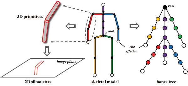
Motion capture involves not only tracking motions, but also processing and understanding the tracked information. For instance, a digital human model is essential for both processing and visualization the captured motion data. Human bodies can be modeled on different levels of details to meet various requirements. Most of the motion capture approaches use stick figures to depict the tracked motions [ KOF05 ] [ dATS06 ] [ ZH03 ] [ HSD05 ]. In this case, only the skeletal topology and the most significant motion features are visualized. For some vision-based motion capture approaches, human bodies are modeled by 3D primitives [ TMSS02 ] or 2D silhouettes [ GD96 ] to apply image operations. To produce convincing animations virtual characters are almost always modeled with meshes and textures. Recent vision-based approaches can track and animate human models along with the mesh surface directly [ dAST08 ] [ VBMP08 ]. Due to the hybrid nature of our method, we employed a complex human model that comprises different types of information. A skeletal model with basic biomechanical information is used for marker-based tracking and a human model consisting of simple 3D primitives is used for the image-based pose estimation.
Figure 1. Center: The skeletal model consists of rigid bones and ball joints. Right: The bones and joints are organized in a multi-way tree. The root is located at the pelvis. Kinematic chains (encoded with different color) correspond to paths from the root to the leaves. Left: The bones are modeled with cylinders. The silhouettes of the cylinders are calculated and projected on the image plane for the image-based pose estimation.
In marker-based motion capture, the typical way to process the raw captured data is to map the tracked marker coordinates onto a predefined articulated skeletal model. This is often accomplished by a kinematics-based skeletal fitting [ KOF05 ] [ dATS06 ] [ HSD05 ]. Additional heuristics are sometimes employed for better results. Zordan et. al. mapped the marker positions to a character using a physics-based approach [ ZH03 ] and the method proposed by Yu et al. enabled the mapping for multiple characters [ YLD07 ].
Inverse-kinematics-based analyses are often used to control articulated structures such as human models. For a structure with only limited degrees of freedom (DoF), inverse kinematic problems can be solved with closed-form equations [ TGB00 ]. A more general approach to solve an inverse kinematic problem is to linearize the non-linear system using the Jacobian matrix. This linearization leads to numerical IK solvers based on iterative approximation [ WE84 ] [ NH86 ] [ Wam86 ] [ BK05 ].
When the Jacobian matrix is ill-conditioned, its inversion becomes numerically instable. In this case, the articulated structure tends to loose its dexterity and the results provided by the IK solver often show radical oscillations. To address this problem, the Damped Least Squares (DLS) method was introduced [ NH86 ] [ Wam86 ], where the possible radical changes are suppressed by a constant damping factor. However, a constant damping factor also slows down the overall converging speed and leads to more iterations. Buss and Kim introduced Selectively Damped Least Squares (SDLS) method [ BK05 ]. This is an improved version of the DLS method where the damping factor is dynamically calculated according to the current structure configuration. By doing so, the converging speed can be maintained by choosing a smaller factor, while radical changes near the singular configuration can be damped by using a bigger damping factor. As an alternative, Wolovich and Elliot used the transpose of the Jacobian matrix instead of the (pseudo) inverse to increase the numerical stability by sacrificing the precision [ WE84 ]. Besides the numerical stability, many research groups also focused on the utilization of the redundancy in articulated structures. Klein and Blaho discussed a method using secondary tasks to avoid ill-conditioned configurations to some degree [ KB87 ]. Boulic et al. integrated kinetics controllers into the secondary task for statical body balancing [ BMT94 ].
The computer-vision-based motion capturing is an active field of research. Techniques from image processing are intensively employed for the extraction of information from image sequences. This information can be either low-level data such as contours and silhouettes or high-level body features, such as the position of the head or hands. Based on the extracted data, human poses are estimated using appropriate techniques. Gavrila and Davis [ GD96 ] followed an analysis-by-synthesis approach using a contour-based metric for the pose estimation [ WADP97 ]. Stereoscopic or more synchronized cameras are used to perceive the depth information which is absent in 2D images. Visual hulls [ Lau94 ] can be reconstructed based on the coherent multiple views. Visual hulls can be approximated by various 3D primitives, such as voxels or polyhedrons [ CH04 ] [ CMG10 ] [ MBM01 ]. The pose estimation is done by fitting the human model into the visual hull appropriately.
Recently, motion capturing with low dimensional input has been given more attention. Since the information directly gained from the tracking systems is incomplete, procedural heuristics or reference motions are often employed as complements. Grochow et al. [ GMHP04 ] used pre-recorded motions to cope with the ambiguity of the IK-solutions. Chai und Hodgins [ CH05 ] proposed a similar method that is able to capture human motion with reduced markers and two cameras. A stochastic model based on reference motions is used to choose the most likely motion in the case of ambiguity. Although motion databases usually provide realistic reference motions, inappropriate or insufficient motions in the databases directly lead to tracking results of low quality. In addition, the efficiency of such an approach heavily depends on the reduction and organization of the databases as well as the algorithm used for searching in the database.
In this paper we follow a hybrid approach, using both marker positions and monocular videos as input for human motion capturing. We model human body with both a skeletal model and 3D primitives. An inverse kinematics solver adopted from [ BK05 ] is employed to estimate poses with low dimensional marker position data. The video-based pose estimation is similar to the work proposed in [ GD96 ]. However, we use only monocular video in order to achieve a low system complexity. In addition, instead of using a motion capture database as extra reference, we use heuristic functions integrated in the whole algorithm to complete missing information and improve the realism of the estimated results.
For the optical marker-based tracking, the captured motion is a sequence of poses, each of which is estimated according to the marker positions at a certain time. For the vision-based marker-free tracking, the input is the raw image sequence recorded by one camera. We therefore consider the motion capture process as a real-time pose estimation from various input. In the case of simplified marker sets, the available data is not sufficient to determine the poses uniquely. We use inverse kinematics together with the internal constraints of the human model for the pose estimations. Furthermore, image processing techniques are used to extract pose features from the video sequence, providing more constraints for pose estimation. Mathematically, the pose estimation is an optimization in the solution space spanned by the total degrees of freedom of the human model. The solution space is reduced by the constraints defined by the input data and appropriate heuristics. More constraints lead to more precise estimations and thus better tracking results.
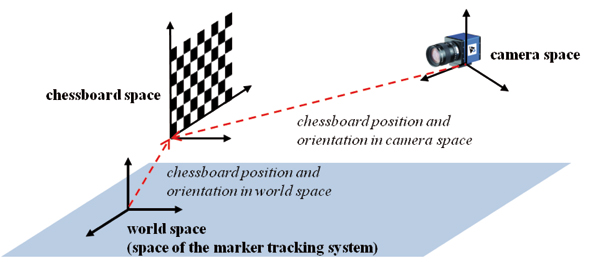
Figure 2. System setup. First, the Marker-based tracking system is calibrated. Then the monocular camera is calibrated using a chessboard pattern. The chessboard pattern is fixed in the world space, which coincides with the space of the marker-based tracking system.
In our approach, we describe the human body as a simplified skeletal model consisting of bones and joints. To reduce the complexity, only those bones that represent major body features are included in the model. Each bone includes values for the parameters length and mass that estimate the values of the corresponding body parts. For the image processing we use cylinders to represent the bones. Therefore a diameter for this cylinder is also part of the bone description. Optionally, a mesh model with textures can be used for an enhancement of the visual feedback.
Table 1. Bones included in our skeletal model. Length in millimeter and mass in gram. All bones except spine, neck and head have two instances.
|
Name |
Length |
Mass |
DoFs |
|
spine1 |
156 |
5790 |
1 |
|
spine2 |
171 |
5790 |
1 |
|
spine3 |
142 |
4130 |
1 |
|
neck |
90 |
3520 |
2 |
|
head |
100 |
4390 |
0 |
|
clavicle |
190 |
4130 |
0 |
|
humerus |
300 |
2180 |
3 |
|
radius |
350 |
1310 |
1 |
|
hand |
80 |
520 |
0 |
|
hip |
85 |
5715 |
0 |
|
femur |
386 |
10050 |
3 |
|
tibia |
550 |
3510 |
1 |
|
foot |
128 |
1110 |
0 |
For each joint the axes and ranges for possible rotations are specified. The number of rotational axes of a joint defines the Degrees of Freedom (DoF) of this joint. Our skeletal model has 21 DoFs in total (see Tab. 1). For the IK solver we define five end effectors: one end effector is placed on each hand and foot and one is on the head. The positions of the head end effector and both hand end effectors are tracked by the marker-based tracking system, each with one marker set. The positions of the feet end effectors are estimated, under the assumption that the feet do not move during the tracking.
Since each bone has exactly one joint, the skeletal model can be described as a multi-way tree. The root of the tree, which is a virtual joint, is placed at the pelvis to complete the tree hierarchy (Fig. 1 right). Because of the 1-to-1 relation between the bones and the joints, these terms can be interchanged. For instance, a rotation of a bone is equivalent to a rotation about the joint that belongs to it and a kinematic chain with n joints must have n links and vice versa.
The IK solver fully utilizes the tree structure by extracting kinematic chains from it. When defining end effectors at the tree leaves, the kinematic chains correspond to paths from the root to leaves. To apply the image operations, we make use of the volumetric representation of the bones. The silhouettes of the cylinders representing the bones are calculated and then projected on the 2D image plane for the image-based pose estimation (details in Sect. 5).
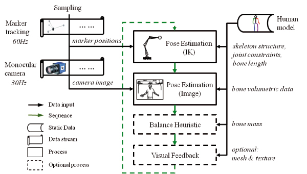
Figure 3. System overview and workflow. A pose is estimated based on the marker positions using an IK solver, and then it is improved by the image-based pose estimation. After that, a balance heuristic is applied for further improvement before the resulting pose is visualized. Marker positions and monocular video are updated at different frequencies but both data streams are sampled simultaneously.
The setup of our hybrid tracking system is illustrated in Fig. 2. After the marker-based tracking system is calibrated, we can choose its coordinate system to be the world coordinate system. Then we calibrate the monocular camera using a chessboard pattern. The chessboard pattern is fixed such that their edges are aligned to the world coordinate axes. After measuring the position of the origin of the pattern we can calculate its corner point positions in the world space. With this information we can determine the camera's position and orientation in the world space using the approach from [ Zha99 ]. This calibration process can also determine the camera's intrinsic parameter. We need both of extrinsic and intrinsic parameters for the image-based pose estimation.
The workflow of our approach is illustrated in Fig. 3. The pose estimation is a sequential process that is repeated at each frame. The marker positions, monocular video and the predefined skeletal model are used as the system input. Since the marker positions are more reliable than the features extracted from the video images, the poses are first estimated based on the marker positions using an IK solver, and then the monocular video is used for a second round of pose estimation. We also use a balance heuristic to improve the results after the two estimation phases. Finally, the estimated pose is rendered for visual feedback.
The marker-based tracking system and the camera work independently of each other, therefore we consider their input as two independent data streams. Upon the beginning of the IK-based pose estimation, the marker positions and the video image are sampled from both streams simultaneously, so that both estimations work on the newest tracking data. Note that the time stamps of the two items are usually different because the two tracking systems work with different frequencies. The resulting frequency of the hybrid system depends on the efficiency of the algorithm and is approximately 24 Hz.
The skeletal model can be regarded as an articulated structure, the poses of which are uniquely defined by the joints' orientations. For an articulated structure with n total DoFs, all the joints' orientations can be described by a vector θ = (θ1,...,θn)T . The scalar θi represents a rotation about the axis defined by the i-th DoF.
The vector θ is the configuration of this articulated
structure at a certain time. We further denote the Cartesian
positions of the k end effectors by a vector s ∈
 3k
. The
pose estimation using inverse kinematics is based on the
expression [
Lie77
]:
3k
. The
pose estimation using inverse kinematics is based on the
expression [
Lie77
]:
 . (1)
. (1)
The Jacobian matrix J = (∂si/∂θj)i=1,...,k;j=1,...,n
consists of the partial derivatives of each end effector's
position with respect to each rotation angle. The matrix
J† represents the pseudo inverse of J. The vector
Δs∈
3k
is the target vector which describes the desired
displacement of the end effectors and Δθ contains the
angular changes of the DoFs in the structure. While
controlling the end effector positions being the main task,
the vector Δφ ∈
n
is an pose configuration that
is determined by the secondary task. The operator
I - J†J guarantees that a secondary task does not affect
the end effector positions. The configuration of the
articulated structure are updated by applying Δθ.
As a result, the end effectors are moved to the new
positions, which in turn, are determined by the direct
kinematic:
 . (2)
. (2)
After the evaluation of (1) and (2) the end effectors may still not be at their target positions. A new Δs is then determined and this evaluation is repeated until the end effectors reach their destination, or the number of iterations exceeds a predefined limit. The iterative algorithm of the IK solver is outlined in Alg. 1.
Algorithm 1. Pose Estimation Using IK
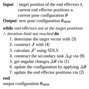
As mentioned in section 3, our skeletal model includes 5 end effectors. In the marker-based tracking we use three marker sets corresponding to the end effectors on both hands and the one on the head. The captured positions of these marker sets at a certain time are the target positions of the corresponding end effectors. The target positions of the end effectors on both feet are chosen such that the feet stay on the ground without moving. Let s and t be the vectors describing the current and the target end effectors positions, respectively, then the target vector is simply
 . (3)
. (3)
Obviously, the neccesary angular increments Δθ increase with the magnitude of Δs. Big angular changes in a single iteration can result in radical pose changes. To avoid such artifacts, we scale the magnitude of Δs to one-tenth of the arm length. In fact, the clamped target vector indicates the desired moving direction of the end effectors rather than the desired displacement. The clamping leads to more iterations but the overall numerical stability of the IK solver is improved.This clamping mechanism is also employed in [ BK05 ].
In equation (1), all the DoFs in the kinematic chain are treated equally in terms of the rotation angle. In other words, there is no priority to perform the rotations while accomplishing a given task (i.e. moving the end effectors to their target positions). However, the human joints need different amounts of energy for a rotation by the same angle. And thus there are joints with higher priority than the others. For instance, as long as the target is reachable, rotations around the elbow are always preferable to those around the shoulder.
This knowledge is used to achieve more realistic tracking results in the case of the low dimensional input. We use the technique introduced in [ Bus03 ], using a weighted Jacobian matrix J = (∂si/∂ψj)i=1,...,k;j=1,...,n instead of the normal one. For the j-th DoF, there is ψj = μjθj , where μj reflects the cost of a unit rotation of about the axis defined by the DoF j. Given the same cost, the DoF with a smaller weight can perform a rotation with a greater angle. In other words, the DoFs are now treated equally in term of the rotation cost rather than the angle. Each element in the weighted Jacobian matrix is then [ BM96 ]
 . (4)
. (4)
In (4) the vector si is the position of the i-th end effector. The vector pj and vj represent the position and the rotation axis of the j-th DoF, respectively. Because of the introduction of the weights, the evaluation of (1) results in rotational costs Δψ (instead of Δθ). We then obtain the angle changes viaΔθi = Δψi/μi . These are used to update the configurations.
To calculate the pseudo inverse of the Jacobian matrix with improved numerical stability, we employ the Selectively Damped Least Squares (SDLS) method introduced in [ BK05 ]. The SDLS method is able to determine a dynamic damping factor according to the current configuration. Its key idea is to estimate the ratio of the desired end effector displacement to the displacement that would actually occur without any damping. The damping factor is then chosen proportional to this ratio.
With Singular Value Decomposition, the Jacobian matrix is rewritten as J = U∑VT Accordingly, the pseudo inverse is then
 , (5)
, (5)
where ui and vi are the orthonormal basis of U and V, respectively. The scalars σi are the r non-zero singular values of J, with r being the rank of J. From ( 1) and ( 5) there is
 . (6)
. (6)
To address the numeric instability that occurrs as one of the σi approaches zero, we introduce upper bounds γi for each term in ( 6). The equation ( 6) then becomes
 . (7)
. (7)
The function ClampMaxAbs(w,d) scales the vector w such that the biggest component of w has an absolute value d. The upper bounds, γi , are the maximal allowed rotation angles for the i-th term. They are determined by
 (8)
(8)
In fact, the scalar Ni is a measurement of the desired end effector displacement and Mi estimates the end effector displacement that would occur if no damping is applied. The factor Γ is a user-defined global maximum of rotation angles.
A pose computed with the described method has nearly correct end effector positions (in the sense of least squares) but still may look very unrealistic. Therefore we implement the secondary task proposed in [ BMT94 ] to improve the realism of the tracking result.
This secondary task is based on the observation that a realistic pose is usually a relaxed one. In other words, let a user-defined pose with the configuration ω be a very relaxed pose, then the estimated pose with the configuration θ could be regarded to be realistic when the difference (ωi - θi)2 is small for each DoF angle. (This would correspond to a section task -2 ∙ (ωi - θi) in ( 1)). Following [ BMT94 ], the effect of the secondary task can be improved by taking the effort of minimizing the angle difference into account as well. This effort is estimated by the static torques (torques caused by gravity) exerted on the DoFs.
For this, we define the i-th augmented body to consist of all the body parts between the root and the joint that has the i-th DoF. An augmented body can be easily extracted from the bones tree. The mass of the i-th augmented body is denoted by mi . Let hi denote the horizontal distance between the i-th DoF and the center of gravity of mi , then the torque exerted on the i-th DoF is proportional to mi ∙ hi . Finally we obtain a secondary task Δφ that reduces the difference of the estimated pose to the most relaxed pose as
 . (9)
. (9)
The video input is used to modify the configuration θ that has been computed by the IK method. The basic idea is to create a 2D image by projecting the volumetric representation of the skeletal model with configuration θ. The error between this image and a corresponding video frame defines the target function that has to be minimized. The arguments of the target function are the components of θ.
A similar approach to compute the angle configuration of an articulated structure from multi-view images has been used in [ GD96 ]. Our approach is different in several aspects. Most important: we use monocular video to improve the results of an IK solver. For the optimization the Downhill-Simplex method is used, with the pose estimated by the IK solver being the start of the optimization.
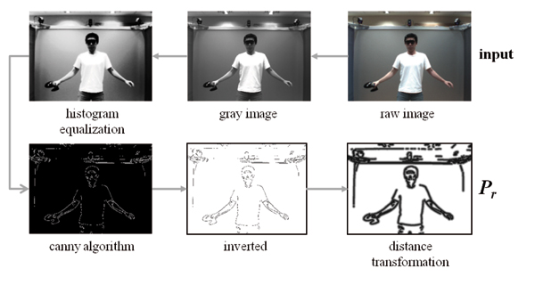
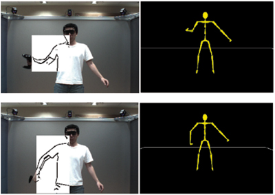
At the time when the marker positions are sampled, the video frame nearest to this sampling time is extracted from the video stream. This raw image is first converted into 8 bit gray images to reduce the computational complexity of the following image operations. A low-pass filter is then applied to remove the noise and a histogram equalization is applied to reduce the negative influence of inappropriate lighting situations. Then the Canny algorithm is applied to extract the edges from the image. Finally, a distance transformation [ BTBW77 ] is applied on the inverted edge image (Fig. 4). The resulting image represents the real pose and it is denoted by
 (10)
(10)
where W and H are the width and height of the
raw image, respectively. Each pixel in
 r
has a value
proportional to the sum of the distances to the nearest
pixels that belong to the edges extracted by the Canny
algorithm.
r
has a value
proportional to the sum of the distances to the nearest
pixels that belong to the edges extracted by the Canny
algorithm.
Let θ be the configuration of the IK-based pose that is estimated from the marker positions sampled together with this video frame, then the volumetric representation of the pose θ is projected onto the camera's projection plane. This projection is actually a 2-phase-mapping: The volumetric data given in the global reference frame is first transformed into the camera's local reference frame, before it is projected onto the camera's projection plane. This whole projection can be denoted by a 4-by-4 matrix
 , (11)
where Mintr is determined by the intrinsic parameters of the camera and it defines the perspective projection from the camera's 3D space to the 2D image plane. The matrix Mextr is determined by the camera's extrinsic parameters, the camera orientation and the position of the center of projection. The extrinsic parameters are given in the global reference frame. Both intrinsic and extrinsic parameters are acquired during the camera calibration using the approach from [ Zha99 ].
The 2D silhouettes of the projection is discretized
according to the given image resolution. This yields a
binary image
s
with
 . (12)
In
s
, pixels with the value 1 form the 2D representation
of the estimated pose with the configuration θ. Therefore,
the difference between these two images can be expressed
as
 . (13)
Now we define the target function as
 . (14)
The additional term λ ∙ ||t - s|| with a big positive λ is introduced to suppress the movement of the end effectors during the optimization. Note that they are already positioned by the more reliable marker-based tracking and the IK solver. The vector t denotes the target positions of the end effectors and s denotes the end effector positions of the currently estimated pose. Since λ is chosen rather big, configurations with end effectors away from their target position are discarded during the optimization.
The downhill simplex method is employed to search for the minimum of C in the solution space spanned by the n DoFs (θ1,...,θn). Although this method does not guarantee a global minimum, in practice a good local minimum can be located by starting the search from the IK-based pose.
To speed up the computation of the optimized configuration, we split the optimization into separate subproblems. More precisely, we optimize the 2 kinematic chains for the arms in separate processes. This reduces the computational time because the low dimensionality of each subproblem results in much faster optimization processes.
Moreover, we are now able to apply the computationally intensive image operations only in small Regions of Interest (RoI) rather than in the whole image. For each process, W and H correspond to the resolution of the RoI and vectors t and s correspond to the positions of the target and the end effector of the currently processed kinematic chain. For instance, the RoI corresponding to the kinematic chain consisting of the right shoulder, the right elbow and the right wrist is illustrated in Fig. 5. This RoI is determined by the 2D bounding box containing the shoulder, elbow and hand joint positions on the image plane. These 2D positions are projected from the estimated pose via (11).
Since neither the IK solver nor the image-based pose estimation takes the balance condition into account, the estimated poses can be out of balance. As shown in the top row of Fig. 6, such a case can occur during a squat movement. To achieve balance of the estimated poses, we employ an additional heuristic.
Figure 6. Applying the heuristic function to maintain balance during a squat movement. Top row: without the heuristic. Bottom row: with the heuristic.
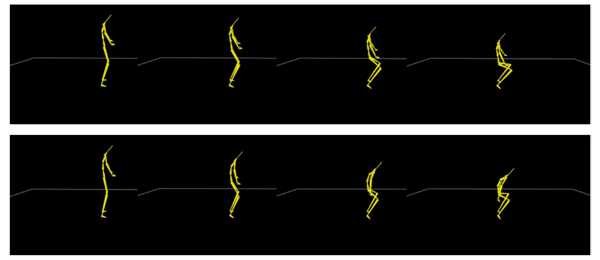
The character is in balance when the horizontal projection of Center of Gravity (CoG) lies in the base of support. The base of support is a 2D bounding box spanned by the supporting positions on the ground (e.g. the positions of the feet).
We noticed that the projected CoG moves out of the base of support mostly during a movement that changes the height of the root. The effect of the height change can be compensated by a forward bow of the character. This is realized by rotating the elements of the spine around an axis orthogonal to the sagittal plane. (The sagittal plane is an vertical plane that divides a body into left and right halves.) Let τi describe the angle of such a rotation applied on the i-th bone of the spine (see Tab. 1), we define all τi for each estimated pose such that they are proportional to the vertical change Δh of the root position with respect to its initial position: τi = pi ∙ Δh, 1 = 1,2,3.... The constant factors pi , which depend on the anthropometric measures of the human model, are set based on our experiments when the skeletal model is adjusted to the specific measures of the human that is going to be tracked.
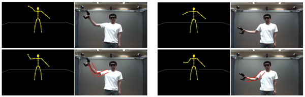
Figure 7. Image-based pose estimation improves poses estimated by the IK solver. Top left: The pose of the right arm is estimated only by the IK solver. Bottom left: The same pose after improved by the image-based optimization. Right column: An other example.
The whole system works with a refresh rate of 20-24Hz, which is sufficient for a visually continuous real-time application. Typical movements in the table tennis application were tracked and the results are illustrated in Fig. 9. No marker calibration is required since the marker sets are installed in wearable or handheld objects. The balance during a squat movement is achieved by the described heuristic (Fig 6 bottom row). This computation needs less than 1ms.
From the visual inspection of the stream of poses in the table tennis application, we got the impression that the marker-based tracking already provides quite realistically looking poses. However, the comparison of individual poses computed with and without the video-based optimization revealed that in many situations the 2-phase pose estimation provides much better results (see Fig. 7).
To evaluate the precision of estimated joint positions precisely, we introduced an additional marker set that is attached on the right elbow of the test subject. This marker set was not involved in the pose estimation but was only used for the evaluation of the results. In the following, the positions delivered by this additional marker set are used as references to be compared with the estimated positions.
As the main result, we found that the differences between the marker provided and the estimated elbow positions significantly decrease when the video-based optimization is included in the pose estimation. The red solid curve in Fig. 8 shows the Euclidean distances between the two positions for the IK-based estimation while the blue dashed curve shows these distances when the video-based optimization is switched on. The improvement achieved by the video-based optimization is clearly shown in the middle diagram of Fig. 8. Initially, the average distances between the measured and the estimated elbow positions is 15.3cm. This value reduces to 10.7cm when the video-based optimization is turned on. However, the video-based pose estimation introduces high frequent position changes, which correspond to small pose oscillations. These positional changes can be better visualized by applying a high pass filter to the error diagram (Fig. 8 bottom). Possible remedies for this unwanted effect are discussed in section 7.
Furthermore, tracking errors in the case of some special movements can still been noticed. Especially, the movement perpendicular to the camera plane is difficult to track precisely because of the lack of the depth information.
Figure 8. Analysis of the results at the elbow. Red solid: values without video-based optimization. Blue dashed: values with video-based optimization. Top: Error between the estimated and the reference elbow positions. Middle: Error reduction by using video-based optimization. Bottom: Error filtered with the high pass filter (>0.3 Hz).
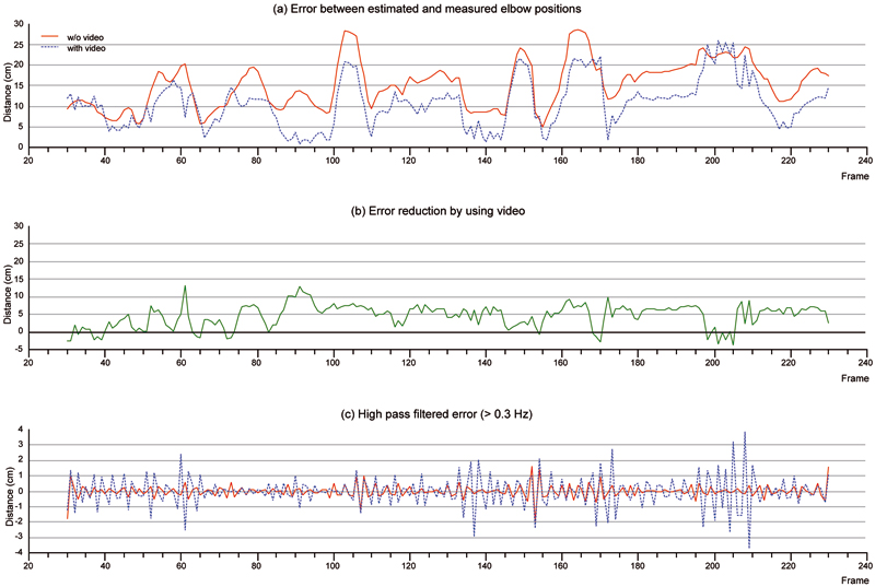
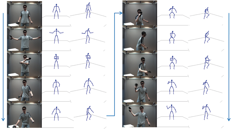
Figure 9. Tracking in a table tennis application. Three marker sets are used. One is installed on the 3D-glasses and the other two are installed on two handhold objects held in each hand. Columns from left to right: the raw video frame, two views of the estimated pose, and the same for the column group on the right. Arrows indicate the sequence of the poses.
In this paper, a hybrid method for real-time human motion capture using simplified marker sets and monocular video is presented. After establishing a simplified human model, poses are estimated from the tracked marker positions and optimized based on the monocular video sequence. An improved inverse kinematic solver is employed for estimating the poses based on the marker positions. An analysis-by-synthesis approach is used for refining and improving the poses based on the video images. A speed up of the computation has been achieved by splitting the optimization into subproblems and performing the image operations on appropriate subsets. Furthermore, a fast heuristic was employed to keep the character in balance during squat movements.
In the application, human motions could be captured in real-time without a laborious marker calibration. For this we followed a sequential approach. That is, the video-based estimation uses the IK-result and the balancing process works on the pose after the video-based optimization. Moreover, each process modifies only a specific part of the pose estimated in the previous phase. The video-based optimization only modifies the arm configuration but leaves the positions of the hands unchanged. The balancing process modifies only the spine configuration.
This is done, because the marker-based tracking system provides reliable end effector positions and the IK is computationally less intensive than the image processing. Since all subsequent steps are based on the poses provided by the IK solver, these poses should be estimated as accurate as possible. Therefore the authors are working on the integration of dynamic factors (e.g. speed and acceleration) to improve the marker-based pose estimation.
The image-based optimization also introduced high frequent position changes into the solution. There are two possible sources for this unwanted effect. First, the inaccuracy of the image processing introduces noise in the data used for the optimization. Second, our method does not employ any temporal coherence in the application of the downhill simplex function. These problems could be coped with a low-pass filter that is used to remove the high frequent oscillation.
Due to the computational complexity of the image operations, the efficiency of these image operations is the bottleneck of this method. The authors intend to improve the efficiency with a future parallel implementation of the image processing algorithms.
The authors would like to acknowledge the anonymous reviewers for the many valuable comments and suggestions.
[BK05] Selectively Damped Least Squares for Inverse Kinematics, Journal of Graphics, GPU, & Game Tools, (2005), no. 3, 37—49, issn 2151-237X.
[BM96] Hierarchical kinematic behaviors for complex articulated figures, Interactive computer animation, 1996, pp. 40—70, Prentice-Hall, Inc., London, isbn 0-13-518309-X.
[BMT94] Inverse Kinetics for Center of Mass Position Control and Posture Optimization, Workshop in Computing Series, 1994.
[BTBW77] Parametric correspondence and chamfer matching: two new techniques for image matching, IJCAI'77: Proceedings of the 5th international joint conference on Artificial intelligence, San Francisco, CA, USA, 1977, pp. 659—663, Cambridge, USA, Morgan Kaufmann Publishers Inc., isbn 0-934613-48-6.
[Bus03] 3-D Computer Graphics: A Mathematical Introduction with OpenGL, 2003, Cambridge University Press, pp. 317—318, isbn 9780521821032.
[CH04] Real-Time Markerless Human Body Tracking with Multi-View 3-D Voxel Reconstruction, In Proceedings of BMVC, 2004, pp. 597—606, isbn 1-901725-25-1.
[CH05] Performance animation from low-dimensional control signals, ACM Trans. Graph., (2005), no. 3, 686—696, ACM, New York, NY, USA, issn 0730-0301.
[CMG10] Markerless Motion Capture through Visual Hull, Articulated ICP and Subject Specific Model Generation, Int. J. Comput. Vision, (2010), no. 1-2, 156—169, Kluwer Academic Publishers, Hingham, MA, USA, issn 0920-5691.
[dAST08] Performance capture from sparse multi-view video, ACM SIGGRAPH 2008 papers, SIGGRAPH '08, 2008, Los Angeles, California, pp. 1—10, Article no. 98, ACM, New York, NY, USA, isbn 978-1-4503-0112-1.
[dATS06] Automatic learning of articulated skeletons from 3D marker trajectories, In Proc. Intl. Symposium on Visual Computing (ISVC 2006), 2006, pp. 485—494, isbn 3-540-48628-3.
[GD96] 3d model-based tracking of humans in action: A multi-view approach, Proceedings CVPR '96, 1996 IEEE Computer Society Conference on Computer Vision and Pattern Recognition, 1996, San Francisco, CA, USA, pp. 73—80, isbn 0-8186-7259-5.
[GMHP04] Style-based inverse kinematics, ACM Trans. Graph., (2004), no. 3, August, 522—531, ACM, New York, NY, USA, issn 0730-0301.
[HSD05] Self-Calibrating Optical Motion Tracking for Articulated Bodies, VR '05: Proceedings of the 2005 IEEE Conference 2005 on Virtual Reality, 2005, pp. 75—82, IEEE Computer Society, Washington, DC, USA, isbn 0-7803-8929-8.
[KB87] Dexterity measures for the design and control of kinematically redundant manipulators, Int. J. Rob. Res., (1987), no. 2, 72—83, Sage Publications, Inc., Thousand Oaks, CA, USA, issn 0278-3649.
[KOF05] Skeletal Parameter Estimation from Optical Motion Capture Data, CVPR '05: Proceedings of the 2005 IEEE Computer Society Conference on Computer Vision and Pattern Recognition (CVPR'05) - Volume 2, 2005, pp. 782—788, IEEE Computer Society, Washington, DC, USA, isbn 0-7695-2372-2.
[Lau94] The Visual Hull Concept for Silhouette-Based Image Understanding, IEEE Trans. Pattern Anal. Mach. Intell., (1994), no. 2, 150—162, IEEE Computer Society, Washington, DC, USA, issn 0162-8828.
[Lie77] Automatic Supervisory Control of the Configuration and Behavior of Multibody Mechanisms, Systems, Man and Cybernetics, IEEE Transactions, (1977), no. 12, 868—871, issn 0018-9472.
[MBM01] Polyhedral Visual Hulls for Real-Time Rendering, Proceedings of the 12th Eurographics Workshop on Rendering Techniques, 2001, pp. 115—126, Springer-Verlag, London, UK, isbn3-211-83709-4.
[NH86] Inverse kinematics solutions with singularity robustness for robot manipulator control, Journal of Dynamic Systems, Measurement, and Control, (1986), 163—171, issn 0022-0434.
[TGB00] Real-Time Inverse Kinematics Techniques for Anthropomorphic Limbs, Graphical Models, (2000), no. 5, 353—388, issn 1524-0703.
[TMSS02] Combining 2D Feature Tracking and Volume Reconstruction for Online Video-Based Human Motion Capture, In Proceedings of Pacific Graphics 2002, 2002, pp. 96—103, isbn 0-7695-1784-6.
[VBMP08] Articulated mesh animation from multi-view silhouettes, SIGGRAPH '08: ACM SIGGRAPH 2008 papers, Los Angeles, California, 2008, pp. 1—9 ACM, New York, NY, USA, isbn 978-1-4503-0112-1.
[WADP97] Pfinder: Real-Time Tracking of the Human Body, IEEE Transactions on Pattern Analysis and Machine Intelligence, (1997), no. 7, 780—785, issn 0162-8828.
[Wam86] Manipulator inverse kinematic solutions based on vector formulations and damped least-squares methods, IEEE Trans. Syst. Man Cybern., (1986), no. 1, 93—101, IEEE Press, Piscataway, NJ, USA, issn 0018-9472.
[WE84] A computational technique for inverse kinematics, Proc. The 23rd IEEE Conference on Decision and Control, 1984, pp. 1359—1363, Las Vegas, NV, issn 0191-2216.
[YLD07] Online Motion Capture Marker Labeling for Multiple Interacting Articulated Targets, Computer Graphics Forum, (2007), no. 3, 477—483, issn 1467-8659.
[Zha99] Flexible camera calibration by viewing a plane from unknown orientations, Seventh International Conference on Computer Vision ICCV, Volume 1, 1999, pp. 666—673, isbn 0-7695-0164-8.
[ZVDH03] Mapping optical motion capture data to skeletal motion using a physical model, SCA '03: Proceedings of the 2003 ACM SIGGRAPH/Eurographics symposium on Computer animation, 2003, San Diego, California, pp. 245—250, isbn 1-58113-659-5.
Fulltext ¶
-
 Volltext als PDF
(
Size
2.5 MB
)
Volltext als PDF
(
Size
2.5 MB
)
License ¶
Any party may pass on this Work by electronic means and make it available for download under the terms and conditions of the Digital Peer Publishing License. The text of the license may be accessed and retrieved at http://www.dipp.nrw.de/lizenzen/dppl/dppl/DPPL_v2_en_06-2004.html.
Recommended citation ¶
Liang Zhang, Guido Brunnett, and Stephan Rusdorf, Real-time Human Motion Capture with Simple Marker Sets and Monocular Video. JVRB - Journal of Virtual Reality and Broadcasting, 8(2011), no. 1. (urn:nbn:de:0009-6-28196)
Please provide the exact URL and date of your last visit when citing this article.
