Document Actions
CVMP 2010
A Video Database for the Development of Stereo-3D Post-Production Algorithms
- David Corrigan Trinity College Dublin
- Francois Pitié Trinity College Dublin
- Marcin Gorzel Trinity College Dublin
-
Gavin Kearney
 University of York
- Valerie Morris Royal College of Surgeons in Ireland
- Andrew Rankin Trinity College Dublin
- Mark Linnane Trinity College Dublin
- Mick O'Dea Royal Hibernian Academy
- Clive Lee Royal College of Surgeons in Ireland
- Anil Kokaram Trinity College Dublin
Abstract
- submitted: 2011-05-22,
- accepted: 2012-03-15,
- published: 2014-01-14
Keywords
- URN: urn:nbn:de:0009-6-37805
-
swd:
- 1038691184
- 4536854-5
A Video Database for the Development of Stereo-3D Post-Production Algorithms
urn:nbn:de:0009-6-37805
Abstract
This paper introduces a database of freely available stereo-3D content designed to facilitate research in stereo post-production. It describes the structure and content of the database and provides some details about how the material was gathered. The database includes examples of many of the scenarios characteristic to broadcast footage. Material was gathered at different locations including a studio with controlled lighting and both indoor and outdoor on-location sites with more restricted lighting control. The database also includes video sequences with accompanying 3D audio data recorded in an Ambisonics format. An intended consequence of gathering the material is that the database contains examples of degradations that would be commonly present in real-world scenarios. This paper describes one such artefact caused by uneven exposure in the stereo views, causing saturation in the over-exposed view. An algorithm for the restoration of this artefact is proposed in order to highlight the usefulness of the database.
Keywords: video-database, post production, stereo 3D
Keywords: video-database, post production, stereo 3D
SWD: Postproduktion, Videobearbeitung
The commercial success of productions like Avatar [1] has confirmed the public demand for stereo-3D cinema. Advances in digital post-production, projection and camera technologies have made acquiring consistently high quality stereoscopic footage realisable [ Hor08 ]. The success of the Ocula suite of plugins [2] has demonstrated the enabling role of image processing techniques for the post-production of stereo-3D cinema. The addition of an extra view in the pipeline brings with it the extra challenges of processing twice the amount of data as well as synchronising effects between the two stereo views. However, it also affords many opportunities for the development of new technologies when it is considered that there are now two largely views (i.e. the views have a high mutual information [ Sha48 ]) of an object that are temporally synchronised and so are unencumbered with the issues associated with object motion between neighbouring frames of a video.
A quick glance at the Ocula toolset reveals many of the tasks important in the post-production of stereoscopic content. The first issue to note is the need for colour balancing between the two stereo views. Colour imbalances arise due to differing polarisations of cameras, differing camera sensor characteristics or differences between the camera lens settings. Another important task is stereo pair rectification [ HZ03, Ch. 11 p. 302] which removes the vertical disparity caused by either physical misalignment of the cameras or the keystoning effect. Perhaps the most critical task undertaken is the process of disparity estimation which, amongst other things, allows for editing of depth and enables the creation of virtual views. However, this merely represents the tip of the iceberg in terms of the potential of stereoscopic post-production tools.
Access to typical footage is needed to allow researchers to better understand the technical challenges involved in post-production. However, content creators are reluctant to share their content and, consequently, a lack of access to content is a roadblock to research. To date, there is no existing stereo or multiview database specifically designed to meet the needs of research into post-production technologies. The well established Middlebury database [ SS02 ] is used as a benchmark for quality assessment of disparity estimation algorithms but is limited to still stereo pairs. Other databases exist for performing perceptual quality experiments of stereo video [ GSE10, Mob13 ], human interaction [ HKL06, GKH09 ] or in the field of stereo video coding [ SMM09 ].
This paper introduces a database of stereo-3D video designed to address this issue and is freely available for research purposes. It aims to provide representative examples of footage generated during a typical production. The database consists of sequences shot in a number of different settings, both indoors and outdoors, under controlled and uncontrolled lighting conditions. It also contains footage shot from a fixed rig on a tripod as well as footage from a steadicam rig.
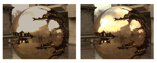
Figure 1. An example of the problem of stereo-view saturation. The images show the stereo pair for this frame after colour correction described in [ PK07 ] is applied. The left view is saturated in the reflected region on the sphere and in the background sky.
We have also added B-Format Ambisonic Recordings to some of the stereo video sequences. Developed in the early seventies by [ Ger73 ], Ambisonics theory models the soundfield impinging on a sphere surrounding the microphone as a weighted linear combination of a number spherical harmonic basis functions. The use of Ambisonics ensures flexibility with multichannel loudspeaker systems (e.g. stereo, 5.1 surround sound etc.) since the recording method is decoupled from the reproduction format. It also presents some advantages over pairwise-mixing based technologies, most notably smooth, artefact-free continuous panning. The second addition to the database is inclusion of sequences shot with a stereo mirror rig. This allows recording of artefacts which are specific to sequences shot on a mirror rig.
To show how we expect the database might be used by researchers, this paper presents a restoration case-study using content from the database. We refer to the stereo-artefact in question as stereo-view saturation. This occurs when unbalanced aperture and gain settings cause one of the views to be much brighter than the other and this results in saturation in the brighter view (See Figure 1). Much of the global brightness imbalance can be corrected using a example-based colour grading algorithm such as [ PKD07, PK07 ]. However, such a technique will not recover the high frequency detail lost. In this paper we introduce an approach to this problem of stereo-view saturation. It recovers the missing detail using wavelet decompositions to transfer high frequency information from the clean view to the saturated view.
The rest of the paper is divided into two main parts. First of all, the database is introduced. We describe the technical aspects of the shoot and discuss the composition of each shot in the sequence. The second part of the paper discusses the stereo-view saturation case-study, outlining an algorithm for its restoration. We then conclude by discussing the importance of disparity estimation to achieving a high quality restoration.
Execution of a variety of shooting scenarios is an essential requirement for our database. One important consideration is the choice of shooting location. This has the obvious effect on the lighting conditions as well as the degree of control over them. The database consists of 3 broad categories of locations: in studio, on-location indoors and on-location outdoors.
The studio location offers a greater degree of control over the lighting conditions. The studio used for the shoot contained a lighting rig consisting of 8 650W spot lights with a support frame suspended from the ceiling on which the lights could be mounted. For the indoor on-location sequences, shooting took place inside a pub. This presents a more challenging lighting scenario. Pubs generally contain low levels of ambient light and its tight confines permit only limited amounts of additional lighting. Finally, a large portion of the database is shot outdoors. The main difficulty here is the changeable nature of the lighting conditions which requires frequent changing of the camera exposure settings.
The second requirement of the database is that it consists of content that is interesting in the context of post-production. In large part, this involves the replication of scenarios familiar to the post-production of 2D video. Challenging lighting conditions are one aspect of this, with the associated problems of colour-grading and denoising of contrast enhanced video. Another important aspect is the class of motion estimation or tracking and matting scenarios, and a particular focus was given to generate difficult content for these applications. Finally, the database should contain scenarios and artefacts specific to stereo-3D video.
Figure 2. (a) Side-by-Side Rig (b) Mirror Rig The two photos show the rig used to record the sequences in the database. The interocular distance and convergence point are changed by adjusting the screws on the rig. On the mirror rig these settings are changed by adjusting the screws for the horizontally-mounted camera.
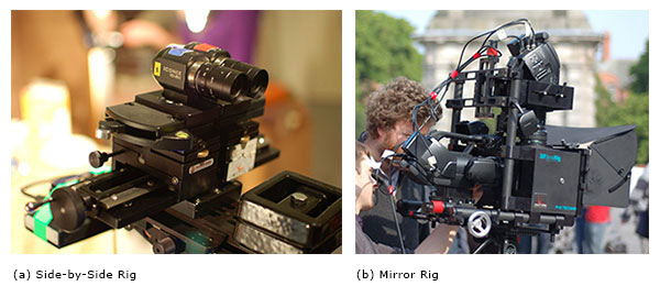
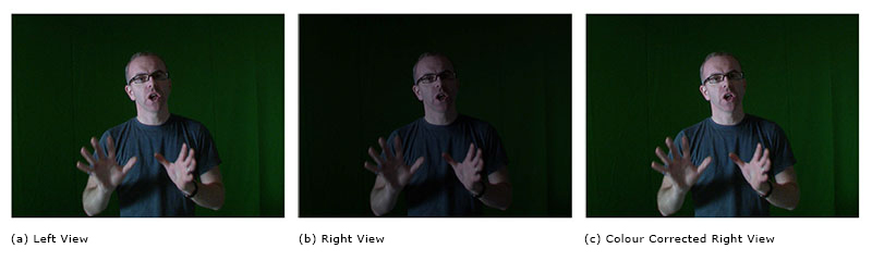
Figure 3. An example of the colour imbalance between the left and right views. (c) shows the right view after colour using the Pitié and Kokaram algorithm [ PK07 ].
The videos contained in the database were shot using two different stereo camera rigs. The majority of the sequences were shot using a rig consisted of two Iconix HD-RH1 cameras [3] mounted on an Inition 'bolt' side-by-side adjustable rig [4] (Fig. 2). The rig allows for significant control over the camera geometry including adjustment of the interocular distance, camera tow-in, tilt and roll. The rig is mounted on either a tripod or steadicam.
Two pairs of matching lenses were employed: a 4-mm wide angle lens and an 8-mm lens used for close-ups. Due to the camera control hardware being external to the actual camera casing and the small 1/3 inch camera sensor, it is possible to obtain interocular distances using a side-by-side mounting less than that over the average human interocular distance.
Camera Synchronisation is provided via a genlock signal generated by one of the camera control units. The data itself was recorded using two separate Flash XDR [5] units. It encodes the data using the XDCAM 4:2: 2"xd5e" codec at a bit rate of approximately 100 Mbps. All of the footage gathered is 24-bit colour at a resolution of 1920x1080 pixels and at a frame rate of 25 fps progressive. The left and right sequences are also embedded with matching timecodes to facilitate easy temporal alignment of the two views.
The second rig used consists of two Sony PMW-EX3 cameras mounted on a P+S Technik 'standard' mirror rig. This rig allows for the adjustment of the interocular distance and convergence point and can achieve arbitrarily small interocular separations do to the configuration of the camera in the rig. The cameras have a 1/2 inch CMOS sensor and are both fitted with a zoom lens with a focal length range of 5.8 to 81.2 mm. The recorded videos are synchronised by feeding a genlock signal between the cameras. The video data itself is recorded onto camera-mounted SxS cards. The data is encoded to the MPEG-2 standard using a 4:2:0 variable bit rate encoder up to a maximum bit rate of 35 Mbps. Similarly to the side-by-side configuration all sequences have a resolution of 1920x1080 pixels and at a frame rate of 25 fps progressive.
The interocular distance and convergence are the two most important parameters affecting the sensation of depth. Increasing the interocular distance scales up the sensation of depth while adjusting the convergence point effectively translates the scene along the depth axis. Due to their importance, many modern camera rigs employ motors to simplify and make more precise the adjustment of these settings. The design of intuitive interfaces for their adjustment has received some attention recently [ HGG11 ]. However, neither the side-by-side nor mirror rig allow for motorised adjustment and so all adjustments were made manually. Although manual adjustment leaves more scope available for misalignment of the cameras, the database is designed to capture many of these artefacts to facilitate the development of post-production techniques for their removal and so automated control is not essential.
The lighting setup was dictated by the choice of location. For the sequences captured in-studio, studio lighting was employed. As stated previously, the studio lighting setup consisted of 8 650W lights and an above head height frame suspended from the ceiling and a control panel that allowed the intensity of each light to be adjusted individually. In contrast, additional lighting in the on-location sites was more sparingly used. In fact, no additional lighting was used in the outdoor shots. For the indoor location, there was a limited amount of additional lighting provided by a 300W spot and a 4-bank Kino Flo lighting fixture [6].
The basic philosophy behind the studio lighting design was to illuminate the performance area from a single key light and two diffuse fill lights to soften shadows cast by the key. The diffuse lighting was provided by two of the 650W spot lights mounted at head height at either end (ie. left and right from the camera perspective) of the performance area, with a screen of frosted glass placed in front of each light to provide diffusion. The other lights are placed on the frame suspended above the performance area. Their function was primarily to provide the keylight, although some were also used to provide additional illumination to the backdrop.
The choice of camera mounting is another important consideration. The database contains sequences shot on rigs mounted on either a tripod or a steadicam. The choice was often dictated by the confines of the location or a desire for mobility.
Furthermore, due to the weight and size of the mirror rig, it is not possible to use a steadicam with the rig. Other considerations are the choice of focal lengths, choice of interocular distance, the focus of both cameras and the convergence point of the two views. When using the Iconix cameras on the side-by-side rig the 4mm lens was used for most sequences, although the 8mm lens is used for some of the close ups. The interocular distance is 35mm for all the sequences. The focal length on the Sony EX3 cameras mounted on the mirror rig is typically set manually by finding the most appropriate focal length for the scene and carefully matching the focal lengths of thecameras.
However, the method for setting the focus and convergence point varied depending on the location. For tripod-mounted shots, it was possible to fix the focus range to the performance area. The convergence point is then set to ensure that the action is perceived to take place behind the plane of the screen when displayed. This is achieved by placing some form of vertical rule at the required convergence point and adjusting the interocular distance and tow-in until there is zero disparity at the convergence point. Achieving such precise settings for the focus and convergence is more difficult when the steadicam is used because the distance to the closest object varies greatly. For the studio and indoor on-location clips, the convergence point and focus and convergence point is set by making an educated guess of the minimum object distance. The convergence point is set similarly for the outdoor shots. However, the focus point of the two cameras is set to near infinity to maximise the amount of the scene in focus.
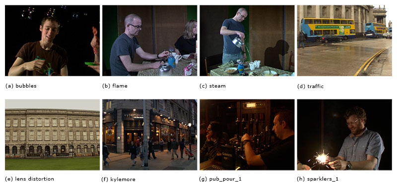
Figure 4. Eight left view frames from different sequences in the database. The caption under each fame indicates the value of the name id for each sequence.
Correcting colour imbalances between views is a common task when processing stereo video. After a preliminary examination of the database, noticeable colour distribution differences between stereo pairs were observed in nearly every sequence shot. Colour imbalances are generally caused by either differing camera settings for each view or differing polarisations of the incident light on each camera. The nature of the colour imbalance varies depending on the cause. Intuitively, camera settings differences cause a colour imbalance that manifests as a global warping of the colour distribution, as the spatial content of the views is largely similar and the factors affecting the imbalance are spatially invariant in nature. On the other hand, polarisation differences create an imbalance that is spatially varying. This difference affects the choice of algorithm that should be employed.
Correction of such colour imbalances falls into the category of example-based colour transfer problems, whereby the colour distribution of one image is mapped onto that of another. First formulated in [ RAGS01 ] the problem has received much interest in works such as [ AK04, NN05, PKD07, PK07 ] [7]. The algorithm outlined by Pitié and Kokaram in [ PK07 ] is perhaps the most useful method to consider as it is well suited to situations where the imbalance is global in nature. It provides a linear transformation for colour transfer based on a Monge-Kantorovich formulation of the problem. Hence, it has nice monotonic properties. For example, the brightest and darkest points remain the brightest and darkest points after transfer. It is also more computationally efficient and more robust to artefacts when compared with the non-linear colour transfer algorithm of [ PKD07 ].
In the online database, the sequences have been restored using the algorithm of Pitié and Kokaram [ PK07 ]. First of all the colour statistics of one of the two views are chosen as a reference view that possesses the desirable distribution for the pair. The other view is then modified to match the statistics of the first while the first view remains unaltered. In order to avoid high frequency flicker in the modified view a fixed transformation is used for each frame in this sequence. The first frame of each sequence is used to estimate the transformation between the views and this transformation is then applied to the remaining frames of the sequence.
The 3D Audio recordings in the database are presented in Ambisonics B-Format. Ambisonics attempts to estimate the audio-induced pressure field defined on a notional sphere surrounding the 3D microphone.
In [ Ger73 ], Gerzon outlines a compact representation of the pressure field as a linear combination of a limited number of lower-order time-varying coefficients of a spherical harmonic decomposition of the sound field. The simplest representation of the soundfield that allows localisation is known as first order Ambisonics which uses the zeroth order and 3 first order spherical harmonic coefficients only. This is also known as B-format Ambisonics. The coefficients are represented as W, X, Y and Z channels. The W channel corresponds to an audio signal recorded with a microphone that has an even gain in all directions (the zeroth order harmonic). The X, Y and Z channels each correspond to an audio signals recorded with a figure-of-eight response (the first order harmonics or velocity components) that record sound along front-back, left-right and vertical axes respectively.
The main strength of Ambisonics over other surround sound formats is its ability to pan the sound smoothly around the listener without audible artefacts like comb filtering. This is because in Ambisonics every speaker contributes to the localisation of the sound field at all times. This is in contrast to the pairwise mixing technique in which only a subset of the speakers contribute and so, as sound sources pan, different speakers will switch on and off. Audio recorded in the Ambisonics format also gives superior localisation of sounds to the back and especially to the sides [ Ger85 ]. Furthermore, the B-Format specification is completely independent of speaker layout, unlike other popular multichannel microphone array configurations [ The00 ]. A dedicated Ambisonics decoder allows the B-Format audio to be converted into the appropriate speaker signals on-site. This allows the customised rendering of the audio for optimal playback depending on the shape of the room and number of speakers. Furthermore, if a decoder is not available, it is possible to pre-convert the B-Format audio into other surround sound formats such as stereo or 5.1 surround.
Two different recording devices attached to the stereo rig were used to generate the audio contained in the database. For the scenes that were recorded in the studio, a SoundField MK5 System was used to capture the audio signals. This SoundField microphone uses four closely spaced cardioid or sub-cardioid microphone placed at the corners of a tetrahedron [ Ger75 ]. For the other locations a Zoom H-2 recorder [8] was used. This recorder contains front and rear facing stereo microphones and post-processing allows the signals from both these microphones to be converted into B-Format Ambisonics. However, it is not possible to create a Z channel with the Zoom recorder and consequently only sound sources on the horizontal plane can be localised. An additional audio channel recorded with a shotgun microphone [9] is recorded for the studio sequences that contain dialogue. This data can be mixed with the Ambisonics channels toobtain a more defined dialogue signal.
As stated in section 2.1, the recording devices used encode the video data in compressed video formats. In order to make them freely available, the sequences are converted into LZW-compressed indexed tiff sequences. For each sequence, the database contains both the original and colour corrected versions.
At the highest level, sequences are organised according to the stereo rig with which they were shot. Each category is then sub-divided into sequences which have accompanying audio and those that have not. At the bottom level, files are named according to the following convention "name.location.rig.mount.processing.view.dddd.tiff". Here, the name is a unique identifier for each sequence. The location string represents the location where the sequence is shot and can have a value of "std" for the studio location, "ind" for the indoor on-location set and "otd" for the outdoor sequences. The rig and mount ids describe the video capture equipment used. Rig is either "sbs" for the side-by-side rig or "mir" for the mirror rig and mount is either "fix" for a fixed camera or "scm" for a steadicam mounted camera. The processing string dictates what degree of processing applied to the sequence and can have a value of "raw" for the original shots and "col" for colour corrected sequences. Finally, the view represents the individual stereo views (left or right) and "dddd" is a 4 digit frame number. For example "tree.sbs.otd.scm.raw.left.0024.tiff" is the unprocessed left view of frame 24 of the tree sequence which has shot outdoors on a steadicam mounted side by side stereo rig.
Where audio accompanies the video sequences, each channel of the B-Format data is placed in a separate file. The file format used is the uncompressed wav format. The files have 24 bits per sample and a sampling rate of 48 kHz. The file-naming convention used is "name.channel.wav" where name matches the name id for the video sequence. The channel id refers to the audio channel and its possible values are "W", "X", "Y", "Z" and "Shotgun". We also provide Matlab files that allow conversion of the B-Format files so that can be played in stereo and on a 5.1 array.
If the reader wishes to access the database, then contact David Corrigan or Anil Kokaram at the email addresses given in contact information on the first page of this paper. Alternatively, information for gaining access to the database can be found at http://www.sigmedia.tv/StereoVideoDatabase .
The frames shown in Figure 4 represent the breadth of material contained in the database. Many of the pictures shown represent a deliberate attempt to capture an element known to be challenging for post-production. For example, the bubbles (Fig. 4a), flame (Fig. 4b) and steam (Fig. 4c) sequences pose challenges due to the semi-transparent nature of the elements which make them difficult applications such as matting and disparity estimation. Several other sequences such as the traffic sequence (Fig. 4d) are included as potential examples for rig removal [ KCR05 ]. A sequence (Fig. 4e) is also included in the database to highlight the significant lens distortion artefacts caused by the small size of the camera sensors.
The database also represents a taxonomy of defects potentially present in a stereo sequence. Some artefacts are present in nearly all of the sequences. For example, the problem of colour imbalances has been documented previously in this paper but others exist such as image noise. Other artefacts are only apparent in a limited number of sequences. These include the common stereo-video artefacts of keystoning and vertical disparity as well as other image artefacts. An example of this artefact is the flare artefact present in the sparklers sequence which manifests as a vertical streak in the image. Another examples include stereo-view saturation..
The sequences with accompanying audio contain examples with varying degrees of dialogue and ambient sounds. Most dialogue heavy examples are contained in the studio sequences. The sequences shot outdoors contain more ambient noise. Some of these sequences contain moving sound sources such as passing traffic and provide good examples of panning audio sources. The mirror-rig sequences contain much the same content and artefacts as the side-by-side rigs. However, due to the action of the mirror there is a notable red-cast in one of the stereo views. The "drama" sequence shot on the the mirror rig is an example of a stereo sequence where one view is in focus and the other is out of focus.
One of the features of the database is that it brings to light some artefacts that are specific to stereo-3D sequences. One example of this is referred to here as stereo-view saturation (Figure 1). This artefact arose due rapidly changing lighting conditions when filming outdoors (from overcast to rain to bright sunshine) which required frequent changing of the aperture sizes of the lenses. This resulted in a mismatch of the aperture settings of the two cameras, resulting in uneven exposures and saturation or burn-out in the over-exposed view. In this section we present a simple algorithm to restore this artefact which demonstrates the usefulness of the database for research in stereo-3D post-production.
In the 2D world, it would be impossible to recover the saturated detail without resorting to some form of texture transfer or synthesis (for example [ EF01 ]) or image inpainting ([ BSCB00, PGB03 ]). However, if it is assumed that most of the saturated detail can be seen in the other stereo view, and that a reliable estimate of the disparity estimate can be obtained, then it is reasonable to suggest that the missing detail can be transferred from the unaffected view. This observation forms the basis to our approach.
The stereo disparity model is represented by the
following equation
Isat(x) = Iref(x+d) (1)
where Isat
is the view where the saturation occurs and Iref
is the other stereo view, and is referred to here as the
reference view. d represents a per-pixel disparity vector
field that maps pixels from the saturated to the reference
view. The saturated image, Isat
also obeys the following
corruption model
Isat(x) = (1 - α(x))Îsat(x)+α(x)Csat
(2)
where Îsat is the uncorrupted value of Isat , Csat is a constant saturation colour and α is a matte of the saturated areas. It is apparent that Equation (2) closely resembles the matting equation or a model for missing data treatment, however, there are some important differences. First of all, saturation does not occur evenly in the 3 colour channels (the red channel could have more saturation than the blue), so Equation (2) should in theory be applied separately to each colour channel, although in our approach a joint α over the three colour channels is considered. Secondly, unlike the matting equation, the "foreground" or "replacement noise" Csat is a constant value. It will also be the maximum value allowed in each colour channel. Furthermore, Csat is related to the dc solution in the saturated region and so, unlike the missing data case, it need not be considered as a replacement noise process. Therefore, to recover the missing detail only the mid to high frequency content needs to be copied from the reference view.
In this paper, we use the wavelet transform to perform the data fusion. The wavelet transform is suited to this task because it allows the transfer high frequency information while preserving the low frequency information. Indeed, similar image decompositions have been used to solve the related problem of image fusion [ MKR07, BK93, GVWD06 ]. we adopt the Dual Tree Complex Wavelet Transform (DTCWT) [ Kin01 ] to perform the detail transfer. The advantage of the DTCWT is that it can achieve approximate shift invariance with only limited redundancy. The shift invariance property ensures that coefficients can be interpolated to a high degree of fidelity. It is this property of the DTCWT that has given it a wide relevance in many image processing applications including motion estimation [ MK98 ].
In summary, there are three main aspects to this problem: disparity estimation, detection of the saturated regions and then transfer of the texture details from the reference to saturated views. The disparity field d can be estimated from many of the myriad algorithms proposed in the literature [ SS02 ] and, as already outlined, a wavelet based approach is used to perform the detail transfer. In addition, we outline an automatic technique to detect saturated regions based on simple thresholding and morphological operations. The remaining sections of this paper discusses these aspects in details and also outlines the other operations performed during the restoration.
The first stage of processing is a global correction performed using the algorithm outlined in [ PK07 ]. The process is applied in much the same way as it is for the other sequences on the database. However, care is taken to ensure that the colour palette of the saturated view is mapped to that of the reference view as a reverse mapping would mean that intensities in the reference view would be mapped to values outside the valid range. A consequence of this operation is that the colour of the saturated region is shifted such that its value is no longer the the maximum value of the intensity range (eg. 255 for an 8-bit range), and this can be seen in Figure 1.
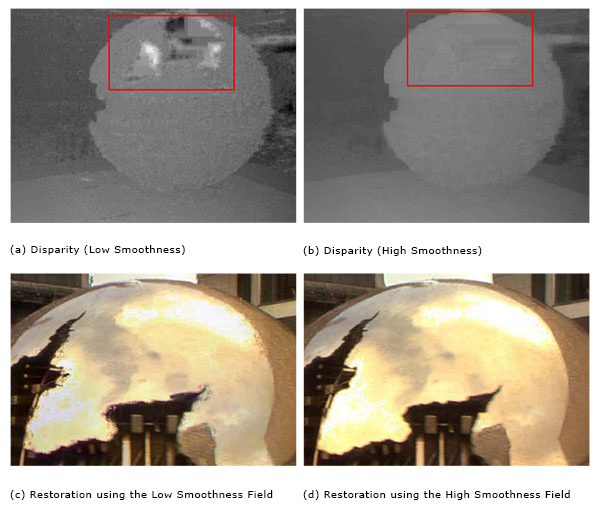
The remaining pre-processing stages are concerned tackling the first aspect of our problem, namely the estimation of disparity between the two views. However before disparity estimation is performed the stereo pair is rectified, ensuring that all stereo correspondences will liealong horizontal lines (ie. d is a scalar field). Here, the "VerticalAligner" Ocula plugin is used to perform the rectification [10]. The disparity field d is then estimated from the rectified pair using the "DisparityGenerator" plugin [11]. This is further compounded when burnout is present, since the texture content in the over-exposed and reference views is different. Hence the disparity estimation is an ill-posed problem in saturated regions. Here, we mitigate this problem by choosing a high spatial smoothness on the disparity estimator. Thus, the disparities inside saturated regions are typically interpolated from the values outside the saturated regions (See Figure 5). Effectively, the assumption is that the texture detail is simply painted onto the surface of the saturated object.
Figure 5. Top Row - An example of the right to left disparity for one frame of the sphere sequence. The red box highlights the field in the saturated region. Since there are no texture features to track in the saturated region, the disparity field is erratic (a). However, increasing the disparity smoothness parameter does a good job of filling in the field in the saturated region (b). For more complex surfaces than a sphere, increasing smoothness may not be sufficient.
In this work, a simple approach to saturation detection is adopted. The basic principle underlying our solution is that the saturated colour is the maximum intensity value. Due the monotonicity property of [ PK07 ], the saturated regions in the colour spectrum will correspond to the brightest point in the image. Since saturation is not uniform across the colour channels, a different saturation field αc for each colour channel c is calculated according to
 (3)
(3)
where
 is the intensity of the colour-corrected and
rectified saturated view in colour channel c. The overall
saturation field α is given by the per-pixel logical-Or of
the individual αc
s.
is the intensity of the colour-corrected and
rectified saturated view in colour channel c. The overall
saturation field α is given by the per-pixel logical-Or of
the individual αc
s.
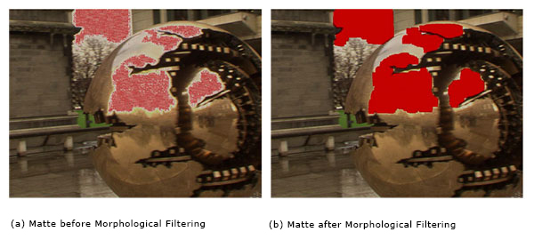
Our tests have shown that choosing an aggressive saturation matte which includes all saturated regions as well as some unsaturated regions, results in fewer artefacts in the restored view. This is achieved using morphological operations. The operations applied are a closing (7 × 7 square structural element) to fill in holes in the saturated region, an opening (7 × 7 square structural element) to remove isolated false alarms in the non-saturated regions and a dilation (7 × 7 square structural element) to ensure that a buffer around the saturated region is included in the matte. Figure 6 shows examples of saturation detection results using this method.
Figure 6. An example of the saturation matte after the thresholding stage and after the morphological filtering stage.
As stated above, detail transfer is performed in the
wavelet domain using the DT-CWT. Initially, the disparity
compensated reference image Ĩref(x+d) is calculated in
the image domain. Then, the saturated view and the
disparity compensated reference view are converted into
the wavelet domain by taking the L-level DT-CWT giving
low-pass bands Lsat
and Lref
and a set of band-pass
sub-bands Bl
sat
and Bl
ref
for l = 1,...,L. The wavelet
coefficient of the restored sub-bands
 are given
by
are given
by
 (4)
(4)
In other words, the wavelet coefficients in the restored
view are a mixture of the coefficients from the unsaturated
regions and interpolated coefficients from the reference
view in the saturated regions. αl
is α downsampled by a
factor of 2l
. The restored image then found taken the
inverse transform consisting of the low-pass band from the
saturated image Lsat
and the restored
.
The major parameter choice is the number of DT-CWT levels L that must be taken. If too few are taken then some of the lower frequency detail will not be transferred to the saturated view. If L is too high, then the result is unnecessary computation. For the sequences shown here, a perceptual evaluation found that between 7 and 9 levels were sufficient in all cases.
Figure 7. Restoration examples of four frames (one on each of the rows) from the three test sequences, where the top three rows represent real examples from the database and the bottom row is from an artificially saturated sequence. The left column shows the left saturated view and the middle column shows the restored result. For the three real examples the rightmost column shows the right stereo view whereas the bottom right picture from the artificially corrupted sequence is the original left view.
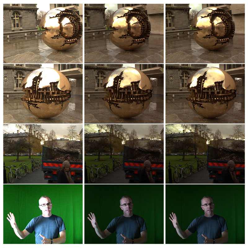
Figure 8. Restored frames from two sequences after the wavelet interpolation stage ((c) and (f)). The detail in the saturated regions is recovered well. Also the interpolation can recover some of the fine detail lost due to the fringing of foreground objects in front of background regions saturated regions. However, the are some low frequency colour fluctuations in the restored frames (eg. the blue tint on the sphere in (c)). These are removed using a second re-colouring stage.
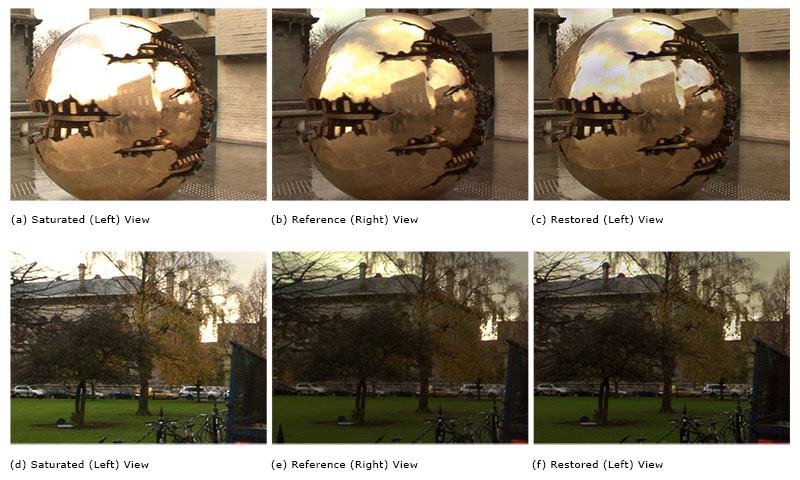
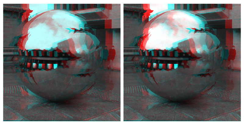
Figure 9. A stereo pair frame before (left) and after (right) restoration rendered in anaglyph form. The reflection on the sphere appears better defined after restoration. Viewing it also results in less eye strain.
Three sequences [12] of 50 frames each were processed to remove saturation (Fig. 7). Two of these sequences exhibit actual saturation in the left stereo view while the left view of the third sequence was artificially saturated by multiplying the pixel values by a constant. Figure 8 provides a visual indication of the typical result achieved after the DT-CWT transfer algorithm. From a texture detail point of view, the restored image compares well to the unsaturated view. It even manages to resolve the fringing artefacts on the borders of the saturated regions (eg. The top left corner of Fig. 8f). However, there is typically a low frequency colour distortion present in the final result (Fig. 8c). This distortion is caused by the mixing of wavelet coefficients from two images with slightly different colour distributions.
As the induced colour imbalance is local rather than global in nature, re-applying the algorithm of Pitié and Kokaram will not remove the artefact. The block-based correction provided in the "ColourMatcher" plugin of Ocula is applied as a final restoration stage. Using a block size of 20 and the disparity estimate generated previously, the colour distribution of the restored saturated image is matched to the distribution of the reference view (See Fig. 10). Applying this correction step almost completely removes the colour imbalance. The true impact of the restoration becomes more apparent when anaglyph representations of the restored and original stereo pairs are examined (Figure 9). This figure indicates a marked reduction in eye strain when viewing the restored pair.
The main strength of the wavelet-based approach is that it facilitates interpolation without prominent seams at the matte boundary. This can be shown more clearly when comparing it against interpolation in the conventional image space. It can be seen from Figure 11 that interpolation in conventional image space will leave seams along the matte boundary in places where edges are not aligned accurately or where there are slight colour differences between the two views. Since low pass filters are used to reconstruct the image from the wavelet coefficients, any seams will be filtered but without any discernible softening of the image.
This work on stereo-view saturation is presented as a case-study to show the potential usefulness of the database. As such, the analysis proposed here represents an initial investigation into the problem. Accuracy of Disparity Estimation is an essential requirement for accurate restoration since accurate disparity estimation is assumed when interpolating between views. In difficult areas for disparity estimation, such as at depth discontinuities or in the saturated regions themselves, artefacts tend to exist. This can be seen in the example on the bottom row of Figure 7 in which the tops of the fingers are smeared across the background due to a lack of resolution in the disparity field at the depth discontinuity. The temporal consistency of the restoration is also directly related to the temporal consistency of the disparity field. Temporally inconsistent disparity estimates result in a noticeable temporal flickering effect in the restored sequences. Furthermore, since texture detail is destroyed in saturated regions, disparity estimation is inherently prone to failure in these regions (Fig 5 ). In spite of this, it may still be possible to achieve a sufficiently accurate disparity estimate. For the examples shown here, using a high spatial smoothness for the disparity estimator of Ocula was sufficient to get a smooth field over the saturated region. However, in general this is not a safe assumption to make. A similar problem exists in the missing data treatment algorithms described in [ Kok04 ], where the interpolated data and motion estimates are iteratively updated. Therefore, a solution to saturation restoration which iterates between detail interpolation and disparity may be possible.
Of course disparity estimation has a wider significance to stereo-3D post-production, and is comparable in importance to motion estimation for 2D post-production. Much research effort has gone into designing disparity estimation algorithms as can be seen from the benchmarking on the Middlebury dataset [ SS02 ]. However, most of the state of the art focus on a single stereo pair and does not consider the issue of temporal consistency when performing disparity estimation on sequences on stereo pairs. It is only recently [ BG09, KCN11 ] that the issue of temporal consistency has started to be addressed. Clearly, this a major area for future work in this field.
In this paper, we have introduced a database designed to provide free access to footage for researchers interested in developing algorithms for stereo-3D post-production. The database contains footage that covers a range of scenarios encountered in a typical production. Another goal is to uncover artefacts that may occur in such footage so that solutions to these problems can be developed. The saturation of stereo views is an example of such a problem and a simple restoration algorithm was provided as a case-study of the potential usefulness of this database.
Figure 10. The restored sphere before (left) and after (final) colour correction using the block-based colour matcher of Ocula. The colour distribution of the final result closely resembles that of the reference view (Fig. 8b ).
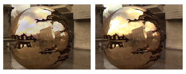
Figure 11. The arrows in the left images highlight visible seams at the matte boundary when the data is interpolated by copying pixels from the reference view. The proposed wavelet based restoration (right) provides a seamless interpolation.
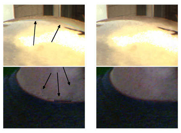
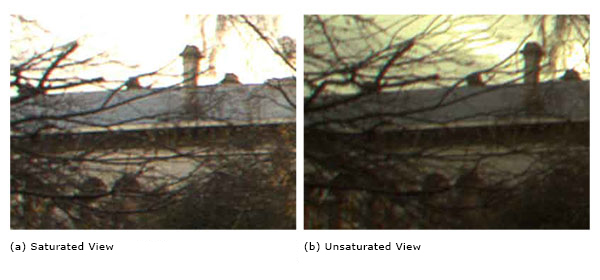
Figure 12. (b) Unsaturated View (a) Saturated View These images are enlarged versions of the images in Fig. 8d and 8e . The area highlighted here shows significant fringing of the branches in front of the sky. It is clear that in some areas the gradient of the branches has been attenuated and not completely reduced. This indicates varying degrees of saturation as opposed to an on/off scenario.
The authors would like to thank John Squires and Fionnuala Conway from Trinity College Dublin as well as Charlie Perera from Inition for their assistance during the recording of the database. This work was funded in part by the Science Foundation Ireland (SFI) PI project CAMP, the EU FP7 project i3DPost and Adobe Systems Inc.
[AK04] A fast and efficient fuzzy color transfer method Proc. of the IEEE Symposium on Signal Processing and Information Technology pp. 491—494 2004 0-7803-8689-2
[BG09] Temporally Consistent Disparity Maps from Uncalibrated Stereo Videos Proceedings of the 6th International Symposium on Image and Signal Processing and Analysis pp. 383—387 September 2009 1845-5921
[BK93] Enhanced image capture through fusion Proceedings of the Fourth International Conference on Computer Vision pp. 173—182 1993 0-8186-3870-2
[BSCB00] Image Inpainting ACM Siggraph pp. 417—424 2000 1-58113-208-5
[EF01] Image Quilting for Texture Synthesis and Transfer ACM SIGGRAPH 2001 August pp. 341—46 1-58113-374-X
[Ger73] Periphony: With-height sound reproduction Journal of the Audio Engineering Society 1973 1/2 2—10 0004-7554
[Ger75] The Design of Precisely Coincident Microphone Arrays for Stereo and Surround Sound 50th Audio Engineering Society Convention 1975.
[Ger85] Ambisonics in Multichannel Broadcasting and Video Journal of the Audio Engineering Society 1985 11 859—871 0004-7554
[GKH09] The i3DPost multi-view and 3D human action/interaction database Proceedings of the Conference for Visual Media Production 2009 pp. 159—168 978-0-7695-3893-8
[GSE10] A Comprehensive Database and Subjective Evaluation Methodology for Quality of Experience in Stereoscopic Video SPIE Three-Dimensional Image Processing (3DIP) and Applications 2010 0277-786X
[GVWD06] Cross dissolve without cross fade: Preserving contrast, color and salience in image compositing Computer Graphics Forum 2006 3 577—586 1467-8659
[HGG11] Computational Stereo Camera System with Programmable Control Loop ACM Transactions on Graphics 2011 4 94.1—94.10 978-1-4503-0943-1
[HKL06] A Full-Body Gesture Database for Automatic Gesture Recognition IEEE International Conference on Automatic Face and Gesture Recognition 243-248 2006 0-7695-2503-2
[Hot08] Future Shock: Why Stereoscopic 3D may be the key business opportunity for Broadcast and Post Quantel June 2008 available at http://www.visionaryforces.com/downloads/Strereoscopic_3D_White_Paper.pdf, last visited October 15th, 2013.
[HZ03] Multiple View Geometry in Computer Vision Cambridge University Press 2003 2nd Edition 0521540518
[KCN11] Spatio-temporal consistency in video disparity estimation IEEE International Conference on Acoustics, Speech and Signal Processing (ICASSP 2011 pp. 885—888.
[KCR05] Automated rig removal with bayesian motion interpolation Vision, Image and Signal Processing, IEE Proceedings 2005 4 407-414 1350-245X
[Kin01] Complex wavelets for shift invariant analysis and filtering of signals Journal of Applied and Computational Harmonic Analysis 2001 3 234—253 1063-5203
[Kok04] On missing data treatment for degraded video and film archives: a survey and a new Bayesian approach IEEE Transactions on Image Processing 2004 3 397—415 1057-7149
[MK98] Motion estimation using a complex-valued wavelet transform IEEE Transactions on Signal Processing 1998 4 1069—1084 1053-587X
[MKR07] Exposure Fusion Proceedings of the 15th Pacific Conference on Computer Graphics and Applications 2007 pp. 382—390 IEEE Computer Society 1550-4085
[Mob13] Mobile3dtv: Video plus depth database 2013 Available online at: sp.cs.tut.fi/mobile3dtv/stereo-video/, last visited October 21st, 2013.
[NN05] Color style transfer techniques using hue, lightness and saturation histogram matching Proc. of Computational Aestetics in Graphics, Visualization and Imaging 2005 pp. 111—122 3905673274
[PGB03] Poisson image editing ACM Transactions on Graphics 2003 3 313—318 1-58113-709-5
[PK07] The Linear Monge-Kantorovitch Colour Mapping for Example-Based Colour Transfer IEE European Conference on Visual Media Production 2007 London pp. 1—9 978-0-86341-843-3
[PKD07] Automated colour grading using colour distribution transfer Journal of Computer Vision and Image Understanding 2007 1-2 123—137 1077-3142
[RAGS01] Color transfer between images IEEE Computer Graphics Applications 2001 5 34—41 0272-1716
[Sha48] A Mathematical Theory of Communication Bell System Technical Journal 1948 379—423, 623—656.
[SMM09] An overview of available and emerging 3D video formats and depth enhanced stereo as efficient generic solution Proc. of the 27th Picture Coding Symposium 2009 pp. 389—392 978-1-4244-4593-6
[SS02] A taxonomy and evaluation of dense two-frame stereo correspondence algorithms International Journal of Computer Vision 2002 1/2/3 7—42 1573-1716
[The00] Multichannel Natural Recording Based on Psychoacoustic Principles Audio Engineering Society Convention 108 5156 2000.
[9] A Sennheiser K6 was used. http://en-de.sennheiser.com/modular-microphone-system-k-6
[11] Much of the state of the art in this field is reference on the Middlebury Database website [ SS02 ]
[12] Videos of the restored sequences can be found at http://www.mee.tcd.ie/~corrigad/research/stereo_desaturation/
Fulltext 
-
 Volltext als PDF
(
Size
19.7 MB
)
Volltext als PDF
(
Size
19.7 MB
)
License 
Any party may pass on this Work by electronic means and make it available for download under the terms and conditions of the Digital Peer Publishing License. The text of the license may be accessed and retrieved at http://www.dipp.nrw.de/lizenzen/dppl/dppl/DPPL_v2_en_06-2004.html.
Recommended citation 
David Corrigan, Francois Pitié, Marcin Gorzel, Gavin Kearney, Valerie Morris, Andrew Rankin, Mark Linnane, Mick O'Dea, Clive Lee, and Anil Kokaram, A Video Database for the Development of Stereo-3D Post-Production Algorithms. JVRB - Journal of Virtual Reality and Broadcasting, 10(2013), no. 3. (urn:nbn:de:0009-6-37805)
Please provide the exact URL and date of your last visit when citing this article.
