Artikelaktionen
VRIC 2008
The MIRELA framework: modeling and analyzing
mixed reality applications using timed automata
urn:nbn:de:0009-6-17423
Abstract
Mixed Reality (MR) aims to link virtual entities with the real world and has many applications such as military and medical ones. In many MR systems and more precisely in augmented scenes, one needs the application to render the virtual part accurately at the right time. To achieve this, such systems acquire data related to the real world from a set of sensors before rendering virtual entities.
A suitable system architecture should minimize the delays to keep the overall system delay (also called end-to-end latency) within the requirements for real-time performance. In this context, we propose a compositional modeling framework for MR software architectures in order to specify, simulate and validate formally the time constraints of such systems. Our approach is first based on a functional decomposition of such systems into generic components. The obtained elements as well as their typical interactions give rise to generic representations in terms of timed automata. A whole system is then obtained as a composition of such defined components.
To write specifications, a textual language named MIRELA (MIxed REality LAnguage) is proposed along with the corresponding compilation tools. The generated output contains timed automata in UPPAAL format for simulation and verification of time constraints. These automata may also be used to generate source code skeletons for an implementation on a MR platform.
The approach is illustrated first on a small example. A realistic case study is also developed. It is modeled by several timed automata synchronizing through channels and including a large number of time constraints. Both systems have been simulated in UPPAAL and checked against the required behavioral properties.
Keywords: Mixed reality systems modeling, real-time, timed automata, formal analysis, simulation, model-checking
Subjects: Simulation, Timed Automata, Mixed Reality
Ensuring real-time properties of mixed reality (MR) systems encounters some obstacles often leading to inefficient, less satisfactory or sometimes even ineffective applications. This is partly due to the growing complexity of such systems, but also to the wide range of available human computer hardware interfaces (sensors) and several kinds of sensorial modalities, each of them giving rise to its own rendering loop. Indeed, sensors as well as rendering loops have their own time constraints, generally different from each other.
Nowadays, the usual process for developing MR applications relies mostly on fast response and high hardware performances to cope with time constraints. Yet, for some applications (for example, robot teleoperation or haptic ones) the respect of time constraints may be critical. It may be worth, in such a context, to validate the application, before testing it on actual hardware, by modeling it and applying formal method techniques to prove its robustness. The benefits may be twofold: it may avoid unnecessary cost related to a possible deterioration of hardware, and in the case of design errors, it allows to identify their sources (in terms of unsatisfied time constraints of components) and to correct them and validate again.
In this paper we are interested in specification and validation of heterogeneous, reconfigurable, open but not hot pluggable MR systems. We propose a compositional modeling framework for software architectures in order to specify, simulate and validate formally their time constraints, as well as to generate a prototype for MR platforms.
Our intention here is not proposing a new formalism, but taking advantage of known time constraints specification and verification techniques in the design and the programming of real-time systems. We chose for this purpose to use a prominent model of timed automata [ AD94 ] and its associated tool UPPAAL [ LPY97 ]. The latter allows simulating systems, verifying, through model-checking, various reachability properties, and detecting deadlocks (meaning that the specified time constraints cannot be met by the system). Typically, it can answer the designer questions which may look like "starting from its initial state, can the system reach a given state in a given delay?".
Our approach is first based on a functional decomposition of such systems into generic components. The obtained elements as well as their typical interactions give rise to generic representations in terms of timed automata and the whole application is then obtained as a composition of such defined components. To ease writing specifications, a textual language is also introduced along with the corresponding compilation tools. The generated output contains timed automata in UPPAAL format for simulation and verification of time constraints.
Once validated, this formal model of the system is used to generate automatically source code skeletons for an implementation on a MR platform.
The paper is structured as follows: After an introductory section exposing the related works, we present intuitively our framework and its main elements, namely a textual language MIRELA, an existing verification and simulation tool UPPAAL and a component based MR development environment ARCS. The sections 3 and 4 are devoted to the presentation of MIRELA syntax and its semantics in terms of timed automata. The sections 5 and 6 illustrate the aspects related to the verification and validation (using existing tools) and the rapid prototyping. A classical MR example is unfolded step by step in order to illustrate the approach. A more important case study is developed in the last section.
Modular software architectures and frameworks for MR have been addressed during these past years by almost thirty different projects of frameworks [ EBM05 ]. Amongst the most remarkable ones, we can mention the StudierStube led by the Technical Universities of Vienna and Graz (Austria) [ Fuh99 ]. This project is based on the OpenInventor API and uses the concept of distributed scene-graphs. One of the sub-projects of StudierStube mainly focuses on sensor configuration issues [ RS01 ] and on data processing aspects after being acquired by sensors. This is performed by using an object-oriented approach combined with software engineering practices, like configuration files written in XML.
The DWARF (Distributed Wearable Augmented Reality Framework) project relies on distributed services. Each tracker becomes a service broadcasting data to other services (that could be filters, rendering loops,...) using an extension of CORBA [ BBK01 ].
ImageTclAR [ OTX03 ] aims to provide a rapid prototyping environment to test and design MR applications. People can use proposed components or develop their own ones in C++ whereas the whole logical glue between components is written using Tcl interpreted scripts.
Tinmith [ PT03 ] is an API for developing mobile AR systems. It uses an object store, which is based on Unix file hierarchy, and allows applications to register callbacks on these objects. Once these objects change (for example, when one sensor acquires a new data set) an event is sent to trigger these callbacks.
The AMIRE (Authoring Mixed Reality) project [ HZHL03 ] emphasizes component based development. This project embeds a graphical tool to connect and configure components. Data concerning the configuration of the application are stored in an XML file.
Finally, the ARCS (Augmented Reality Component System) project [ DOM06 ] is also a component-based framework with graphical tools to help to design MR applications. It focuses on the component life span in running these applications and on the reconfigurability of data flow between components at runtime.
These projects are mostly emphasizing modular development or even component based engineering to deal with the heterogeneity challenge. Of course, our approach is related to the above, but we are especially interested in some real-time aspects of MR applications. Usually, the real-time in the MR field of research may be understood in various ways and seen as a real world time in simulation or as low latency man-machine interactions, or even as a preservation of imposed time constraints. In this paper, we aim at addressing the last point of view which focuses on operational deadlines, from events to system response.
Real-time systems may be specified using numerous dedicated methods and formalisms. Most of them are graphical semi-formal notations allowing a state machine representation of the behavior of the system. Among the most popular formalisms, we may quote Statecharts [ Har87 ] or UML/RT [ Dou97 ].
Such visual representations do not enable the verification of the system properties, and it is necessary to associate a formal semantics to them, based in general on automata, process algebras [ HPSS87 ], Petri nets [ Rei85 ] or temporal logics [ MP92 ].
In our approach, we chose to use timed automata [ AD94 ], which have the advantage to be rather simple to manipulate and possess adequate expressivity in order to model time constrained concurrent systems. Moreover, there exists for this model powerful implemented tools (e.g., UPPAAL [ LPY97 ]) allowing model-checking and simulation.
This section presents a general view of the MIRELA architecture: its basic elements, a general decomposition scheme as well as its main components.
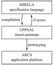
The MIRELA framework is composed of three elements forming a chain as shown in figure 3:
-
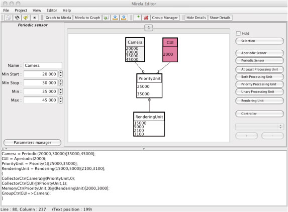
A textual language called MIRELA (for MIxed REality LAnguage) provided with timed automata semantics (forming the core of this approach), coupled with a graphical editor to generate the code using visual metaphor (see figure 1);
-
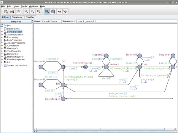
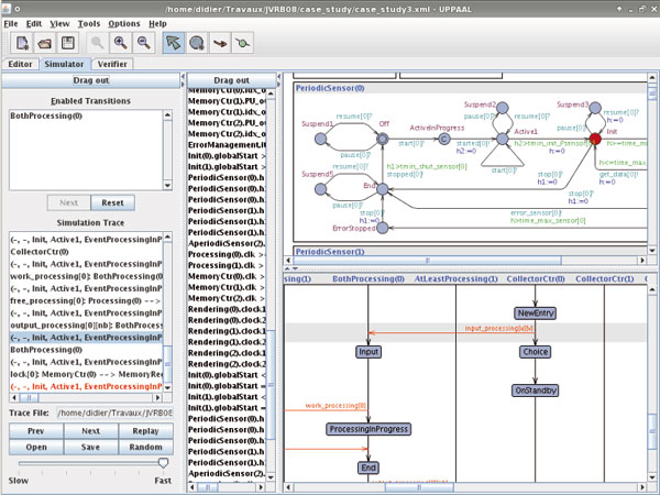
An existing model-checking and simulation tool: UPPAAL which is using its own query language (see figure 2);
-
A component based environment focused on the development of MR applications like ARCS.
The MIRELA framework allows to describe MR applications using a simple specification language. The corresponding code is automatically translated into a system composed of a family of timed automata respecting specified timed constraints. The UPPAAL tool allows to analyze the model of the application. If some errors are discovered at this stage, the specification code may be corrected and this process may be repeated until obtaining a satisfactory solution. Then, the obtained model may be used to generate a prototype of the MR application for a target platform (ARCS).
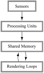
In this paper, we consider MR architectures organized according to a data-flow oriented scheme, from sensors to the actual results produced by the rendering loops. As represented in figure 4, data are produced by sensors (cameras, GPS, motion trackers, ...), then they are processed by processing units (in charge of noise filtering, image processing, ...) and stored in a shared memory where they are picked up by the rendering loops. A rendering loop is a pipeline which processes data and transforms them to the actual rendering result (images or force feedback according to the rendering device, ...).
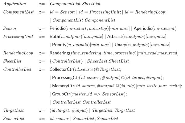
The syntax of MIRELA language follows this decomposition scheme. A MIRELA specification is composed of two parts: a ComponentList declaring all the components like sensors, processing units, and rendering loops, and a SheetList which is a nonempty list of configurations describing how these elements should work together. Such a configuration, called a sheet, is composed of a non empty set of controllers needed to represent the connexions between all the components of the system and to manage sensors conflicts. Declarations of sensors, processing units, and rendering loops are parameterized and relate to time constraints and delays needed for the actual implementation. In particular, each sensor have their corresponding controllers used as their composition interface. We detail below the main characteristics of the elements of the language, its complete syntax is presented in figure 5.
The sensors are devices that capture data from the environment. We assume that each sensor has a unique output (possibly multiplexing sensor's data). The temporal characteristics of the sensors allow us to roughly classify them into two categories:
-
Periodic sensors capture data at periodic time according to a well defined cycle. This periodicity can be expressed by time constraints, corresponding to the minimum and the maximum time of data-gathering. The other time constrains taken into account are the delays to switch sensors on or off.
-
Aperiodic sensors collect data only when an asynchronous event occurs. They may be a representation of a physical sensor (like a switch or any warning device) as well as an abstraction of any system using an event interface (typically graphical user interface). Such sensors have to respect a minimum delay between two events, which can be expressed as a time constraint and is also assumed to be the same as a minimal switch off delay.
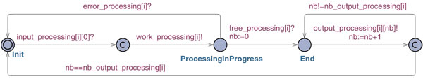
A processing unit (PU) processes data received from sensors. An example of data processing can be an extraction of position and orientation of a camera with respect to its workspace using image processing techniques. A processing unit has time constraints corresponding to the minimum and the maximum time of processing, and may have several inputs and outputs. In our framework, we consider four basic kinds of PUs, that assume the number of inputs is two at most and one at least. This is not a limitation: a PU with more than two inputs may be modeled using a composition of several basic ones.
Each basic processing unit may have several outputs n_outputs, with n_outputs ≥ 1. The outputs are supposed to be triggered sequentially according to their predefined rank comprised between 0 and n_outputs - 1. Accordingly to the kind of PU, we distinguish:
-
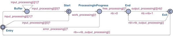
A Unary PU starts processing the data as soon as it is received on its unique input,
-
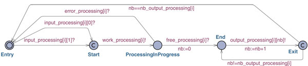
An AtLeast PU starts processing when data are received on at least one of its two inputs,
-
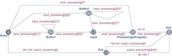
A Both PU has two buffered inputs and starts processing when data are ready in both buffers,
-
A Priority PU has one master input and one buffered slave input. It starts processing when data are ready in master input and possibly uses buffered data from the slave input.
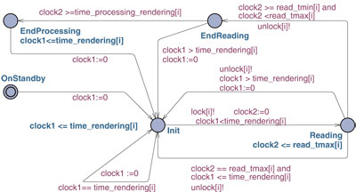
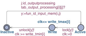
We assume that the memory is composed of registers supporting read and write operations which are mutually exclusive. The rendering loops are periodic and their processing is subdivided in two phases corresponding to the processing and rendering time constraints. Since rendering loops are reading data from memory, the allowed interval of reading is taken into account.
The controllers are components that are used to define a configuration of a MR system by linking different components and managing conflicts that may exist between sensors. There are four kind of controllers:
-
A Collector controller links a sensor to one or several processing units. It broadcasts sensor's data to associated processing units;
-
A Processing controller links two processing units. It connects the output of one processing unit to the input of another processing unit;
-
A Memory controller makes two different links: connects a processing unit output to a memory register and this memory register to a rendering loop unit. This controller has a particularity to take into account the allowed interval of writing down data into the memory register;
-
A Group controller manages conflicts between a sensor and a group of sensors. In other words, if the main sensor is activated, it deactivates (suspends) all sensors into the group it supervises;
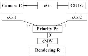
We consider an example of a classical setup for an MR application involving a camera (C) and a graphical user interface (G) with one visual rendering loop. C is modeled as a periodic sensor while G as an aperiodic one. We assume that the camera C may be suspended by the graphical user interface G, which supervises it. Following the philosophy of the language, the corresponding application can be schematically represented as shown in figure 6. The MIRELA code is given below, with constant values referring to time constraints expressed in microseconds.
C = Periodic(20000,30000)[35000,45000];
G = Aperiodic(2000);
Pr = Priority(1)[25000,35000];
R = Rendering(15000,5000)[2100,3100];
{
CollectorCtr(C)@(Pr,0);
CollectorCtr(G)@(Pr,1);
MemoryCtr(Pr,0)@(R)[2000,3000];
GroupCtr(G=>C);
}
The four first lines declare the components of the system:
-
a periodic sensor C with the minimal initialization and switch off delay of 20ms and 30ms, respectively, and of the period comprised between 35ms and 45ms;
-
an aperiodic sensor G with the minimal delay between two events of 2ms (including the switch off event);
-
a priority processing unit Pr with 1 output and the processing time between 25ms and 35ms;
-
a rendering loop R with the rendering time of 15ms, the processing time of 5ms, and the reading time (memory access) between 2,1ms and 3,1ms.
The remaining part describes all the connections between these elements. First, the connection between C and the input port 0 of Pr, and that of G and the input port 1 of Pr are declared. Next, is declared the connection between the output port 0 of Pr and the rendering loop R with the writing time specified between 2ms and 3ms. The last line declares a group with G as a supervisor and a list composed of a unique supervised sensor C; see also the abstract scheme in figure 6 in order to visualize it.
Each element of this functional decomposition will give rise to a timed automaton, as well as the logical glue which links them together. The actual semantics will be obtained by associating to each syntactical element one or more corresponding timed automata, and the whole specification will be given by a parallel composition of all of them.
Before defining timed automata representation of MIRELA specifications, we briefly recall the model and its properties.
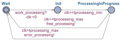
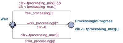
A timed automaton (see figure 7) is a finite state automaton provided with a continuous time representation through real-valuated variables, called clocks, allowing to express time constraints. Generally, a timed automaton is represented by an oriented graph, where the nodes correspond to locations in which the system may be and the arcs indicate a possible location switch. The time constraints are expressed through clock constraints and may be attached to locations as well as to arcs. A clock constraint is a conjunction of atomic constraints which compares the value of a clock x, belonging to a finite set of clocks, to a rational constant c. Each timed automaton has a finite number of locations, one of them being tagged as initial. In each location, the time progression is expressed by a uniform growth of the clock values. In that way, at each instant, the value of the clock x corresponds to time passed since the last reset of x. A clock constraint, called an invariant, may be associated to each location and has to be satisfied in order for the system to be allowed to stay in this location. The arcs may carry clock constraints, called guards, labels allowing synchronization, and indication about clock to be reset.
Figure 7. Example of a timed automaton modeling the processing of a task, where clk is a clock. After the reception of a signal work_processing!, the automaton spends at least tprocessing_min time in the location Init. Then, it sends the signal free_processing! if the processing time does not exceed tprocessing_max, otherwise, it emits error_processing!.
In UPPAAL [ LPY97 ], which is the tool used in our modeling, a timed automaton is a finite structure handling, in addition to a finite set of clocks evolving synchronously with time, a finite set of integer-valuated and Boolean variables. A model is composed of a set of timed automata, which communicate using binary synchronization through arc labels and a syntax of emission/reception. By convention, an arc label k! indicates the emission of a signal on a channel k. It is supposed to be synchronized with the signal of reception, represented by a complementary label k?. Absence of synchronization labels indicates an internal action of the automaton.
The execution of the model starts in the initial state (corresponding to the initial location of each automaton with initial values of all integer and Boolean variables and all clock values set to zero), and is a succession of reachable states. The system state change may occur for three reasons:
-
by time progression corresponding to d time units in the locations of the components, provided that all the location invariants are satisfied. In the new state, the clock values are increased by d and the integer variables do not change;
-
by a synchronization if two complementary actions in two distinct components are possible, and if the corresponding guards are satisfied. In the new state, the corresponding locations are changed and the values of clocks and of integer variables are modified according to the reset and update indications;
-
by an internal action if such an action of a component is possible, it may be executed independently of the other components: the location and the variables of the component are modified as above.
Another peculiarity of UPPAAL, useful in expressing
a kind of synchronicity of moves, is the notion of
" committed" locations, labeled in the figures by a special
label
 ; see, for instance, the location ActiveInProgress in
the automaton of figure 8. In such a location, delaying is
not permitted. This implies an immediate move of the
concerned component. Thus, two consecutive transitions
sharing a committed state are executed without any
intermediate delay.
; see, for instance, the location ActiveInProgress in
the automaton of figure 8. In such a location, delaying is
not permitted. This implies an immediate move of the
concerned component. Thus, two consecutive transitions
sharing a committed state are executed without any
intermediate delay.
A complex system may be represented by a single timed automaton being a product of a number of other timed automata. The set of locations of this resulting automaton is the Cartesian product of locations of the component automata, the set of clocks is the union of clocks, and similarly for the labels. Each invariant in the resulting automaton is the conjunction of the invariants of the locations of the component automata, and the arcs correspond to the synchronization guided by the labels of the corresponding arcs. Due to the presence of real variables (clocks), its behavior defines an infinite state space which may be represented in a finite manner by partitioning it into finitely many equivalence classes so that equivalent states exhibit similar behaviors. This allows it to be analyzed using automated techniques.
In the following, we present an example of a generic timed automaton (template) illustrating one of the main elements composing our system. The remaining timed automata templates (for aperiodic sensors, processing units, memory, rendering loops and controllers) used in our approach are constructed in analogous way and may be found in the appendix. The complete system comprises 16 timed automata templates.
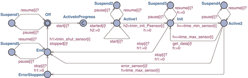
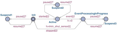
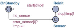
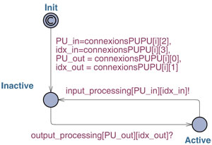
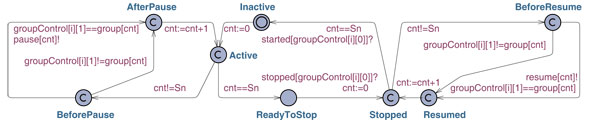
Let us consider the timed automaton in figure 8 showing a modeling of a periodic sensor identified by i. Initially, it is in its initial location Off and its three clock variables h, h1 and h2 are set to 0. At the reception of a signal start[i]! which matches the arc label start[i]?, it moves to the location ActiveInProgress, resets the clock h2 and after spending at least tmin_init_Psensor[i] time in Active1, it arrives to the location Init with the clock h reset to 0. The core of its periodic activity takes place between the locations Init and Active2. Actually, if it is neither suspended nor stopped, it spends at least time_min_sensor[i] time in the location Init, goes to the location Active2, and come back to Init before time_max_sensor[i], reset the clock h and repeats the same behavior again. When working, it may be suspended (and then resumed) or stopped by an external action. It may also happen that it does not meet the specified delays in which case, it launches an error procedure.
The translation to timed automata of our example instantiates the templates defined above for each component of the application. For each line of the MIRELA code, we have at least one instantiated automaton. The resulting model comprises in this case 13 timed automata synchronizing through channels and including a large number of time constraints.
Model-checking is the process of checking whether a given model, in our case the obtained set of timed automata, satisfies a given property, usually expressed as a formula in a query language. To check a property, the model-checker will explore all the reachable states of the system and answer if the property is satisfied or not. It allows in particular to prove that the time constraints specified in the automata are coherent or not with the expected behavior of the system. In UPPAAL, the query language allows to express, for instance:
-
Reachability properties - denoted E<> p (can we reach, starting from the initial state, a state where p is satisfied?),
-
Invariant properties - denoted A[] p (is p satisfied in all states reachable from the initial one?),
-
Temporal implication (or liveness) properties - denoted p --> q meaning that if p is satisfied, then q is satisfied eventually.
The reachability and invariant properties rely only on reachability of states. It means that if the concerned states are potentially reachable, the model-checker will give a positive answer. Generally, it is not enough for guaranteeing liveness properties implying the states to be eventually reached. It means, in particular, that checking such properties make sense only for systems (or fragments of systems) satisfying progress conditions (expressed for example by means of location invariants or committed locations).
It is well known that even for small systems, the number of reachable states may be huge. For instance, it is already about 200,000 states for the example 1, and more than 6,700,000 states for the case study developed in the next section. In practice, this means that it is impossible to analyze it by hand whereas model-checking tools can do it automatically and exhaustively, therefore furnishing a proof.
Example 1. Step III. Table 1 summarizes the queries performed for the example as well as the results returned by the model checker. We should notice that these queries are also used during the modeling process to check if the system has the expected behavior, validating step by step the construction of the model.
Table 1. Queries and results for the example 1.
|
# |
Query |
Result |
|
1 |
A[] not deadlock |
true |
|
2 |
E<> Rendering(0).End |
false |
|
3 |
E<> (PeriodicSensor(0).End and Rendering(0).Reading) |
true |
|
4 |
MemoryRegister(0).Locked --> MemoryRegister(0).OnStandBy |
true |
|
5 |
E<> (MemoryCtr(0).Write and Rendering(0).Reading) |
false |
|
6 |
APeriodicSensor(1).Active --> ( PeriodicSensor(0).Suspend1 or PeriodicSensor(0).Suspend2 or PeriodicSensor(0).Suspend3 or PeriodicSensor(0).Suspend4 or PeriodicSensor(0).Suspend5) |
true |
|
7 |
E<> MemoryCtr(0).Write |
true |
One of the properties we typically want to check is the absence of a deadlock, which is the case and proves the application is meeting its time constraints (cf. Table 1, query 1). However, the absence of a global deadlock does not guarantee that some parts are not locked. For example, if we change the timing constraints in the rendering loop and make an obvious error like having a rendering algorithm spending more time than the period of the rendering loop, then this locks the rendering loop whereas the other parts of the system are still running (cf. Table 1, query 2).
Therefore, we should check the following properties of the system (the answers always confirmed the expected behavior):
-
Is the rendering loop able to perform its task even if the periodic sensor is disabled (cf. Table 1, query 3)?
-
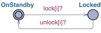
When we lock the memory either for reading or writing, will the memory eventually unlock (cf. Table 1, query 4)?
-
Can we write and read in memory at the same time (cf. Table 1, query 5)?
-
When the aperiodic sensor is activated, will the periodic sensor eventually be suspended (cf. Table 1, query 6)? Since we don't know in which state the periodic sensor will be suspended, we will have to check all suspended states,
-
Can the system write data in memory (cf. Table 1, query 7)?
When a reachability property is answered by true or an invariant property is answered by false, UPPAAL can also produce traces (paths) proving its answer. The model-checker can also look for traces that are the shortest in time of execution or the fastest in terms of steps composing the trace. Using traces makes also possible to obtain some numerical values attached to the properties we want to check. For example, by attaching a clock initialized at the start-up of the periodic sensor, we are able to know the minimum amount of time needed before the first value is written in memory.
However, this query language cannot express some interesting questions about the system. Typically, we cannot express how many times a given state will be reached. That is why model-checker tools are also coupled with simulation tools, the latter ones giving finer indications on the dynamic behavior of the system.
Simulation consists in making automata evolve step by step (manually or randomly) and observing several variables and states of the system. We carried out some simulations for example 1 and the obtained results confirm the expected behavior of the system components at work. It was possible to analyze particular scenarios, like the activation of the aperiodic sensor suspending the periodic sensor. Up to some extent, the simulation provides also some quantitative results, for example, the balance between reading and writing accesses to memory.
A specification composed of timed automata may be used for an automatic code generation for a concrete implementation platform as mentioned in section 3 (see figure 3). However, we need to take into account the difference between theoretical and practical time.
Generally, this problem is handled into two different ways [ AT05 ]. First, the modeling approach advocates including the modeling of the platform on which the actual implementation should take place. In particular, such a modeling will take into account actual communication, initialization, shutdown delays and the delays of process launching.
Second, the semantic approach consists in modeling an abstract view of any implementation platform including tolerance parameters for the various time constraints. It also comprises a theoretical model of a digital clock whichallows time triggered updates of the system.
We use the second approach in order to automatically generate application skeletons for the ARCS platform which is a component-based framework (see figure 3). It is customized to meet the requirements of MR applications (mostly time constraints) and focuses on the design of stand-alone applications.
Each application design consists in a list of components, communication links and initializations. Like any other platform, it relies on a digital clock.
This general architecture has directly inspired the structure of our timed automata modeling and MIRELA language, except the digital clock which has to be added. So, the elements of the modeling can find a natural counterpart in the ARCS environment. Each obtained timed automaton is translated into a component, including the digital clock, except the processing controller which has a direct counterpart in its communication scheme.
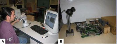
We propose to study the application presented in [ BDK08 ]. It focuses on applying virtual painting on real objects having a priori unknown geometries. This mixed reality interaction involves a probe in the real workspace to touch objects. The probe has a virtual counterpart which is a virtual tool with various physical characteristics. By moving the haptic arm, the user remotely moves the probe. When the probe comes into contact with real objects, it returns forces. These forces are measured and returned to the user combined with virtual forces through by mean of a haptic arm (see figure 9).
Figure 9. Physical setup of the application : A) user workspace with the haptic arm and graphical display; B) real workspace with the camera and the probe.
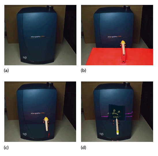
At the same time, a camera is capturing the scene and some image processing is performed to remove the real probe and replace it by the virtual tool. Figure 10 shows the processing steps leading to the final mixed scene. First, a reference image of the real object is taken. Then, the probe is introduced in the real workspace and located in the camera space. Finally, the probe is removed from the real scene using chroma-keying and a virtual tool is overlaid on the image instead of the probe. The painting is also overlaid depending on the forces returned by the probe and the virtual forces computed to simulate the virtual tool.
Figure 10. Mixed scenes taken from the application: a) the real object, here a SGI workstation, b) the probe was painted in red in order to remove it from images later, c) the probe is removed and replaced by a virtual tool, d) virtual painting has been applied on the real workstation.
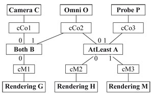
This application involves, in its nominal functioning, a camera (C), a haptic arm (O), a force sensor coupled to the probe (P). Concerning the rendering, both graphical (G) and haptical (H) rendering are performed as well as the mechanical (M) control of the probe, which is assimilated to a rendering loop (see figure 11). The whole is processed by two processing units:
This corresponds to the following MIRELA specification, where the constant values referring to time constraints are expressed in microseconds.
C = Periodic(20000,30000)[35000,45000];
O = Aperiodic(500);
P = Periodic(300000,400000)[300000,400000];
B = Both(1)[20000,30000];
A = AtLeast(2)[500,750];
G = Rendering(15000,5000)[2100,3100];
H = Rendering(1000,200)[100,200];
M = Rendering(400000,200)[100,200];
{
CollectorCtr(C)@(B,0);
CollectorCtr(O)@(A,0)(B,1);
CollectorCtr(P)@(A,1);
MemoryCtr(B,0)@(G)[2000,3000];
MemoryCtr(A,0)@(H)[200,300];
MemoryCtr(A,1)@(M)[100,200];
}
Figure 11 depicts the abstract scheme of the data-flow of the application. In this case, the state space generated during the model-checking process is huge (several millions of states) making it prohibitive for queries demanding to explore it entirely.
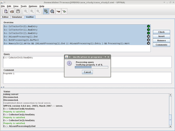
The reachability properties have been checked and their results are summarized in table 2. By answering to these queries, the model checker (see figure 12) can help to determine step by step the data progression through the system. For instance:
-
Do the sensors acquire and transmit data according to their specified time constraints (cf table 2 queries 1-3) ?
-
Is the AtLeast processing unit (A) able to perform its processing (cf table 2 query 4) ?
-
Are the inputs of the Both processing unit (B) able to bufferize the data from one sensor in order to wait for the data coming from the other sensor (cf table 2 queries 5,6) ?
-
Is the system able to put data into memory (cf table 2 queries 7,8)?
The state space is very huge and some queries take very long to be answered (sometimes several hours). For some properties (in particular, reachability ones), it may be more efficient to perform simulations (see figure 13) to observe the behavior of the system. These simulations provide traces (lists of states and transitions between them) that are storing clock values and provide indications concerning time intervals. Therefore, it is possible to evaluate, for example, end-to-end latency of a system (the time the system spends in processing a data from its acquisition to the final rendering), which may be critical for some MR applications [ Azu95 ].
Table 2. Queries and results for the case study.
|
# |
Query |
Result |
|
1-3 |
E<> CollectorCtr(X).NewEntry with x = 1,2,3 |
true |
|
4 |
E<> AtLeastProcessing(1).End |
true |
|
5 |
E<> BothProcessing(0).Buffer2 |
true |
|
6 |
E<> BothProcessing(0).Buffer1 && CollectorCtr(0).OnStandby && |
true |
|
7 |
E<> MemoryCtr(1).Write && (AtLeastProcessing(1).End |
true |
|
8 |
E<> MemoryCtr(2).Write && (AtLeastProcessing(1).End |
true |
In this case study, we can estimate the minimal amount of time needed to acquire data, process them and write them into each memory register. We obtained that the mixed scenes are transmitted to memory in at least 55 ms when the data needed for haptic rendering are transmitted in 500 μs. Since the rendering loops are working with different known time cycles, the minimal end-to-end latency for mixed scenes can be estimated to 73 ms (respectively to 800 μs for haptic data). All these results confirm the model meets the specified time constraints making us reasonably confident about the system implementation.
We introduced in this paper a compositional modeling framework for MR software architectures, initiated in [ DDK08a, DDK08c ] and dedicated to specify and validate formally the time constraints of such systems using timed automata. The presented framework is an extended and completed version of [ DDK08b ] and offers in addition to the previous versions a simple language, called MIRELA, allowing to express in a concise way the elements of the MR architecture with their connections, delays, periods…using generic components. The basic components taken into account are periodic and aperiodic sensors, various kinds of processing units and links (controllers), memory registers and rendering loops. In particular, it is possible to define groups of sensors which may be suspended once another sensor is running. The MIRELA specification is automatically translated into a corresponding set of timed automata representing the given system in order to be analyzed and validated using existing tools (UPPAAL). The approach has been illustrated on a simple example of an MR architecture and used for a realistic case study. In both cases, the corresponding timed automata representations have been simulated in UPPAAL and checked against basic behavioral properties. It permitted to show in particular, that the system in the example was respecting its time constraints. Using simulation cases, it was shown that both systems were meeting their expected behaviors.
In our future work we will be interested in developing a method and tools allowing to use the obtained timed automata model for editing and automatically generating source code skeletons for an implementation on an MR platform. Another direction will be to assist the model-checking process by providing means allowing to abstract specification at an early stage of design. This would result in developing abstraction features to be added to our MIRELA compiler.
[AD94] A theory of timed automata, Theoretical Computer Science, (1994), no. 2, 183—235, issn 0304-3975.
[AT05] Formal Modeling and Analysis of Timed Systems, Implementation of Timed Automata: An Issue of Semantics or Modeling?, Springer Berlin / Heidelberg, 2005, Lecture Notes in Computer Science, , pp 273—288, issn 1611-3349.
[Azu95] Predictive Tracking for augmented reality, Computer Science Department, University of North Carolina, February 1995.
[BBK01] Design of a Component-Based Augmented Reality Framework, Proceedings of the International Symposium on Augmented Reality (ISAR), October 2001, isbn 0-7695-1375-1.
[BDK08] Force feedback virtual painting on real objects: A paradigm of augmented reality haptics, Haptics: Perception, Devices and Scenarios (Proceedings of EuroHaptics 2008), Vol. 5024/2008, Lecture Notes in Computer Science, Springer Berlin / Heidelberg, 2008, 776—785, issn 0302-9743.
[DDK08a] MIRELA: A Language for Modeling and Analyzing Mixed Reality Applications Using Timed Automata, IEEE Virtual Reality 08, Ming Lin, Anthony Steed, and Carolina Cruz-Neira (Eds.), Reno, Nevada , March, 2008, IEEE, pp. 249—250 , isbn 978-1-4244-1971-5.
[DDK08b] The MIRELA Framework: modeling and analyzing mixed reality applications using timed automata, 10th Virtual Reality International Conference, April, 2008, Laval, France, pp. 189—199.
[DDK08c] Modeling and analyzing mixed reality applications using timed automata, 1st Mediterranean Conference on Intelligent Systems and Automation (CISA'08), Juni 2008 , 173-178 Hichem Arioui, Rochdi Merzouki, and Hadj A. Abbassi (Eds.), AIP, isbn 978-0-7354-0540-0.
[DOM06] A Component Model for Augmented/Mixed Reality Applications with Reconfigurable Data-flow, 8th International Conference on Virtual Reality (VRIC 2006), Laval (France), April, 2006, pp. 243—252.
[Dou97] Real-Time UML: Developing Efficient Objects for Embedded Systems, 1997, Addison-Wesley Longman Publishing Co., Inc., Boston, MA, USA, isbn 0201325799.
[EBM05] A Survey of Software Infrastructures and Frameworks for Ubiquitous Computing Mobile Information Systems Journal (2005), no. 1, 41—80, January-March, issn 1574-017X.
[Fuh99] Studierstube: a Collaborative Virtual Environment for Scientific Visualization, Institute of Computer Graphics and Algorithms, Vienna University of Technology, Favoritenstrasse 9-11/186, A-1040 Vienna, Austria, 1999.
[Har87] Statecharts: A Visual Formalism for Complex Systems, Science of Computer Programming (1987), no. 3, 231—274, issn 0167-6423.
[HPSS87] On the Formal Semantics of Statecharts, Proceedings of the Second Annual IEEE Symp. on Logic in Computer Science, LICS 1987, David Gries (Ed.), Ithaca, NY, USA, June 1987 pp. 54—64 IEEE Computer Society Press.
[HZHL03] A generic framework for a training application based on Mixed Reality, Upper Austria University of Applied Sciences, Hagenberg, Austria, 2003.
[LPY97] Uppaal in a Nutshell, International Journal on Software Tools for Technology Transfer (STTT), (1997), no. 1-2, 134—152 October, Springer-Verlag, issn 1433-2779.
[MP92] The Temporal Logic of Reactive and Concurrent Systems, xiv+427, Springer-Verlag, New York, 1992, isbn 0-387-97664-7.
[OTX03] ImageTclAR: A Blended Script and Compiled Code Development System for Augmented Reality, Proceedings of the International Workshop on Software Technology for Augmented Reality Systems, 2003.
[PT03] An Object-Oriented Software Architecture for 3D Mixed Reality Applications, ISMAR '03: Proceedings of the The 2nd IEEE and ACM International Symposium on Mixed and Augmented Reality, p. 247, IEEE Computer Society, Washington, DC, USA, 2003, isbn 0-7695-2006-5.
[Rei85] Petri Nets: An Introduction, Springer, Monographs in Theoretical Computer Science. An EATCS Series, , 1985, isbn 0-387-13723-8.
[RS01] OpenTracker-An Open Software Architecture for Reconfigurable Tracking based on XML, VR '01: Proceedings of the Virtual Reality 2001 Conference (VR'01), p. 285, Washington, DC, USA, IEEE Computer Society, 2001, isbn 0-7695-0948-7.
Volltext 
-
 Volltext als PDF
(
Größe:
4.5 MB
)
Volltext als PDF
(
Größe:
4.5 MB
)
Lizenz 
Jedermann darf dieses Werk unter den Bedingungen der Digital Peer Publishing Lizenz elektronisch übermitteln und zum Download bereitstellen. Der Lizenztext ist im Internet unter der Adresse http://www.dipp.nrw.de/lizenzen/dppl/dppl/DPPL_v2_de_06-2004.html abrufbar.
Empfohlene Zitierweise 
Jean-Yves Didier, Bachir Djafri, and Hanna Klaudel, The MIRELA framework: modeling and analyzing mixed reality applications using timed automata. JVRB - Journal of Virtual Reality and Broadcasting, 6(2009), no. 1. (urn:nbn:de:0009-6-17423)
Bitte geben Sie beim Zitieren dieses Artikels die exakte URL und das Datum Ihres letzten Besuchs bei dieser Online-Adresse an.
-
 News
News